
Instruction Manual
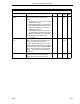
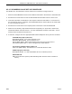
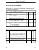
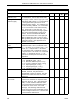
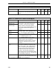

Table 7-3. Siemens PLC Read Control Bytes
Title Definition DDI-A DDI-B Set
By
De-
fault
Error Count* This byte is a running total of PLC Error
Codes and non-zero Communications Error
Codes.
B673 B649 Soft-
ware
0
*User can reset by writing zeros into the datapoints.
Table 7-4. Siemens PLC Write Control Bytes
Title Definition DDI-A DDI-B Set
By
De-
fault
Starting PLC Memory
Address (Low)
The two byte PLC memory address that
states where to start writing data into the
PLC memory. Each byte is a decimal
number; however, both bytes together
function as a 16 bit unsigned binary integer.
(See Siemens Read Control Bytes for
example.)
B675 B651 User 0
Starting PLC Memory
Address (High)
B676 B652 User 0
Number of L-Words
to Write
Count must not exceed 128 bytes total. For
command codes 1 and 2, maximum count
is: L = 64 bytes (512 contacts) and C = 32
words, or L = 0 bytes and C = 64 words.
B677 B653 User 0
Number of C-Words
to Write
B678 B654 User 0
Command Code It is the write command code as follows:
1 = D: DataBlock (word, L & C)
2 = S: Absolute Address (word, L & C)
B679 B655 User 0
PLC Error Code* The PLC Error Codes are reported in
decimal; however, they are listed in
hexadecimal in the PLC manual. See the
Siemens PLC manual for the error code
definitions.
B681 B657 N/A N/A
Communications
Error*
0 = no errors. 255 = timeout error - a
timeout error indicates no response came
back from the PLC. 254 = bad checksum
(CRC) - a bad checksum indicates even
though the frame was formatted properly,
the data can not be used. 253 = bad
message - bad message indicates that
errors were found in the predictable portion
of the message from the PLC. 252 and 251
= PCS hardware malfunction.
B682 B658 Soft-
ware
0
Error Count* This byte is a running total of PLC Error
Codes and non-zero Communications Error
Codes.
B683 B659 Soft-
ware
0
*User can reset by writing zeros into the datapoints.
2 of 2
Section 7. Siemens S5 Mode
SIEMENS
7-5