
Instruction Manual


7.4 CONTROL BYTES FOR SIEMENS
The APB Setup Bytes, PLC Control and Status Bytes, PLC Read Control Bytes, and PLC Write
Control Bytes are presented in Tables 7-1 through 7-4. If any Control Byte is changed during
operation, it takes up to 10 seconds to become effective (there is a 10 second interval be-
tween PCS checks for setup changes.)
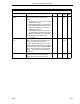
Table 7-1. APB Setup Bytes for Siemens
Title Definition Set
By
DDI-A DDI-B De-
fault
Mode It indicates the APB communications functionality as
follows:
0 = Off, 4 = Siemens
This datapoint should be left at 0 and configured to
a 4 after all of the other control bytes are
configured because setting this datapoint causes
the Siemens PLC Interface functionality to start.
User B290 B456 0
Baud
Rate
It designates the data transfer rate as follows:
10 = 38400, 9 = 28800, 8 = 14400, 7 = 19200,
6 = 9600, 5 = 4800, 4 = 2400, 3 = 1200, 2 = 600,
1 = 300, 0 = 110
User B292 B458 0
Set-Up It designates the data format transfer protocol as
follows:
0 = 8 bits, 1 stop bit, no parity
1 = 8 bits, 1 stop bit, even parity
2 = 8 bits, 1 stop bit, odd parity
User B293 B459 0
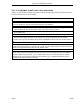
Table 7-2. PLC Control and Status Bytes for Siemens
Title Definition DDI-A DDI-B Set
By
De-
fault
Setup
Error
It indicates the following: 0 = No Error; 1 = L-bytes to
read > 64; 2 = C-words to read > 64; 3 = L-bytes to write
> 64; 4 = C-words to write > 64; 5 = Invalid Command
Code; 6 = Total bytes to read > 128 (command 1 or 2); 7
= Total bytes to write > 128 (command 1 or 2); 8 =
Specifying C-words in commands 3,4,5 or 6; 9 = L-type
data specified for command 3; 10 = Scan Time at 0.
These error codes cause DDI channel operation to halt.
B684 B660 Soft-
ware
0
Scan
Time
It is the PCS time period for the read and write phases
of a PCS-PLC transaction. It is entered as a number
from 1 to 255 which represents 100 to 25,500 ms.
B685 B661 User 0
Scan
Overruns
Counter*
This counter is incremented each time the read-write
phases exceed the specified Scan Time. It indicates the
Scan Time should be increased.
B686 B662 Soft-
ware
0
*User can reset by writing zeros into the datapoints.
Section 7. Siemens S5 Mode
SIEMENS
7-3