
Instruction Manual
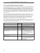
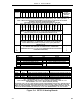
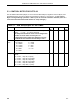
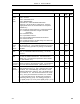
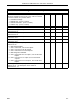
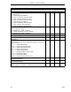

Table 5-4. OPTOMUX Analog I/O Control Bytes
Title DDI-A DDI-B Set By Default
Watchdog Delay on Outputs (PCS ⇒ board) of Each Board
Address 32-39:
0 - Watchdog timer disabled
1 - After 10 seconds, write zero scale.
2 - After 1 minute, write zero scale.
3 - After 10 minutes, write zero scale.
4 - Watchdog timer disabled.
5 - After 10 seconds, write full scale.
6 - After 1 minute, write full scale.
7 - After 10 minutes, write full scale.
B673 B649 User 0
Communication Mode
0 = No data exchange
1 = Reads only - (PCS ⇐ board).
2 = Reads and writes - (PCS ⇔ board)
3 = Writes only - (PCS ⇒ board)
B674 B650 User 0
Number of Contiguous Active Boards 32-39 B675 B651 User 0
Number of Analog Modules on Analog Boards B676 B652 User 0
Number of Contiguous Analog Outputs (in ascending order,
starts with 0)
B677 B653 User 0
Read Analog Command - Uses ASCII code of the letter that
is the command (e.g., 76 for Read Analog Inputs L Positions,
ASCII 76 = L):
76, L, Read Analog Inputs
85, U, Read Input Average Data
108, l, Read Temperature Inputs
97, a, Read Lowest Values
98, b, Clear Lowest Values
99, c, Read and Clear Lowest Values
100, d, Read Peak Values
101, e, Clear Peak Values
102, f, Read and Clear Peak Values
B678 B654 User 0
Analog Input Type for Board Addresses 33 and 37, 32 and 36.
(Enter decimal value.)
B679 B655 User 0
Analog Input Type for Board Addresses 35 and 39, 34 and 38.
(Enter decimal value.)
B680 B656 User 0
Samples to Average (U Command) - Specifies the number of
100 ms samples to be taken. It affects all analog inputs.
B681 B657 User 0
Section 5. OPTO 22 Mode
OPTO
5-11