
Instruction Manual
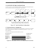

5.3 CONTROL BYTES FOR OPTO 22
The OPTOMUX APB Setup Bytes, PLC Control and Status Bytes, Digital I/O Control Bytes, and
OPTOMUX Analog I/O Control Bytes are presented in Tables 5-1 through 5-4. If any Control
Byte is changed during operation, it takes up to 10 seconds to become effective (there is a
10 second interval between PCS checks for setup changes.)
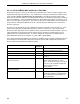
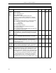
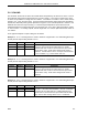
Table 5-1. APB Setup Bytes for OPTOMUX
Title Definition Set
By
DDI-A DDI-B De-
fault
Mode It indicates the APB communications functionality as
follows: 0 = Off, 2 = OPTO 22 Mode
This datapoint should be left at 0 and configured to
a 2 after all of the other control bytes are
configured because setting this datapoint causes
the OPTO-22 PLC Interface functionality to start.
User B290 B456 0
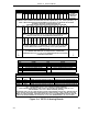
Baud
Rate
It designates the data transfer rate as follows:
10 = 38400 4 = 2400
9 = 28800 3 = 1200
8 = 14400 2 = 600
7 = 19200 1 = 300
6 = 9600 0 = 110
5 = 4800
User B292 B458 0
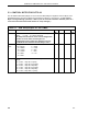
Set-Up It designates the data format transfer protocol as
follows:
0 = 8 bits, 1 stop bit, no parity
1 = 8 bits, 1 stop bit, even parity
2 = 8 bits, 1 stop bit, odd parity
3 = 7 bits, 1 stop bit, even parity
4 = 7 bits, 1 stop bit, odd parity
5 = 7 bits, 2 stop bits, no parity
User B293 B459 0
53MC9015 53MC5000 PLC and Printer Interfaces
5-8
OPTO