
Instruction Manual Owner's manual

Step Procedure
1 Press the
F2
push button and
DO NOT RELEASE IT
.
2
While the
F2
push button is still held pressed, use a paper clip to press the
reset button.
DO NOT RELEASE
the
F2
push button.
3 The display goes all black and then the default display appears.
4
Release the
F2
push button. (The database is reset to the default values with
the default display present on the controller.)
•
If the
F3
push button is held pressed during controller reset, the controller is forced to FIX 0,
Suspend Control State. In FIX 0 the control program stops, inputs continue to be measured,
and totalizers and trends continue to update. Outputs reflect the contents of their associ-
ated datapoints. The logo appears on the display. Use the same proce-
dure provided in the table above (press the
F3
instead of
F2
).
18.7 SUPPLEMENTAL INFORMATION
Schematics and pin assignment illustrations are provided as follows:
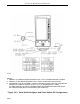
Backplane:
•
Figure 18-2. Hand Held Configurer and Valve Holder Pin Assignments
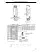
•
Figure 18-3. Cord Set Connector Pin Assignments
Interconnection Terminal Boards (ITBs)
:
•
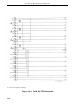
Figure 18-4. Cord Set ITB Schematic
•
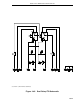
Figure 18-5. Dual Relay ITB Schematic
•
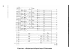
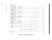
Figure 18-6. 6 Digital Input/4 Digital Output (6DI/4DO) ITB Schematic
•
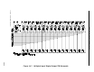
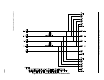
Figure 18-7. 16 Digital Input/Digital Output (16DI/DO) ITB Schematic
•
Figure 18-8. Analog ITB Schematic
•
Figure 18-9. Communication ITB Schematic
Expansion Board Option Cards:
•
Figure 18-10. 6 Digital Input/4 Digital Output (6DI/4DO) PCB Option
•
Figure 18-11. 16 Digital Input/Digital Output (16DI/DO) PCB Option
•
Figure 18-12. Single Channel Analog Input PCB Option
•
Figure 18-13. Multi I/O Analog PCB Option
•
Figure 18-14. High Speed Communications PCB Option
Section 18. Maintenance and Parts List
18-13