INSTALLATION GUIDE Multi-Loop Process Controller 53MC5000 MICRO-DCI.
MicroMod Automation, Inc. The Company MicroMod Automation is dedicated to improving customer efficiency by providing the most ost-effective, application-specific process solutions available. We are a highly responsive, application-focused company with years of expertise in control systems design and implementation. We are committed to teamwork, high quality manufacturing, advanced technology and unrivaled service and support.
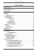
MODULAR CONTROLLER QUICK START Table of Contents 1.0 INTRODUCTION . . . . . . . . . . . . . . . . . . . . . . . . . . . . . . . . . . . . . . . . . . . . . . . . . . 1-1 1.1 DESCRIPTION . . . . . . . . . . . . . . . . . . . . . . . . . . . . . . . . . . . . . . . . . . . . . . . . . . . . . . . . . . . . . . . . . 1-1 1.2 USING THIS MANUAL . . . . . . . . . . . . . . . . . . . . . . . . . . . . . . . . . . . . . . . . . . . . . . . . . . . . . . . . . . . . 1.1 1.3 MODEL NUMBER BREAKDOWN . . . . . . . . .
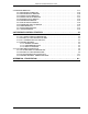
MODULAR CONTROLLER QUICK START 3.4 DATABASE MODULES . . . . . . . . . . . . . . . . . . . . . . . . . . . . . . . . . . . . . . . . . . . . . . . . . . . . . . . . . . 3.4.1 ANALOG INPUT MODULES . . . . . . . . . . . . . . . . . . . . . . . . . . . . . . . . . . . . . . . . . . . . . . . . 3.4.2 ANALOG OUTPUT MODULES . . . . . . . . . . . . . . . . . . . . . . . . . . . . . . . . . . . . . . . . . . . . . . 3.4.3 CONTACT INPUT MODULES . . . . . . . . . . . . . . . . . . . . . . . . . . . . . . . . . . . .
3MC5000 Process Control Station READ FIRST WARNING INSTRUCTION MANUALS Do not install, maintain, or operate this equipment without reading, understanding and following the proper MicroMod Automation Inc. instructions and manuals, otherwise injury or damage may result. Read these instructions before starting installation; save these instructions for future reference. Contacting MicroMod Automation Inc. Should assistance be required with any MicroMod Automation Inc.
MODULAR CONTROLLER QUICK START 1.0 INTRODUCTION 1.1 DESCRIPTION This Quick Start Guide provides the information needed to install and wire a 53MC5000 Modular Controller with a quick and easy set up of two control strategies: CS1 Standard PID and CS20 Two Loop Controller. This guide is designed to help the user become familiar with the 53MC5000 and to place it in service for simple applications.
MODULAR CONTROLLER QUICK START 1.2.3 FLEXIBLE CONTROL STRATEGIES Section 4.0, FLEXIBLE CONTROL STRATEGIES, includes all the information required to set up and place in operation a 53MC5000 Controller using the standard single and two loop control strategies (CS1 and CS20). Listed in a recipe form are all the database parameters that are used by these control strategies. For CS1 Single Loop PID ......................................... see pages 4-1 to 4-6 For CS20 Two Loop PID .............................
MODULAR CONTROLLER QUICK START 1.
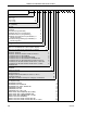
MODULAR CONTROLLER QUICK START 53MC5 _ _ Base Model Number Control Loops 1 One Loop 2 Two Loops 4 Four Loops Power Requirements AC (120/240) 1 DC (24) 2 Functional Requirements Standard Extended (Programmable) Standard w/Factory Configuration Extended w/Factory Programming Standard w/Configuration by Subsidiary or Field Integration Extended w/Programming by Subsidiary or Field Integration Design Level _ _ _ _ _ _ _ _ _ _ _ _ 1 2 3 4 5 6 A B Type Bezel (Design Level "B" Only) DIN 72 x 144 mm
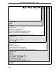
MODULAR CONTROLLER QUICK START 53MC5 _ _ _ _ _ _ Dual Relay ITB Not Implemented One ITB Two ITB’s Three ITB’s Analog I/O Option Not Implemented Single Channel Analog Input Bd Only Multi-Channel Analog I/O Board Multi-Channel Analog I/O Board, Analog ITB Multi-Channel Analog I/O Board, Cable, Analog ITB Multi-Channel Analog I/O Board/HART Option Multi-Channel Analog I/O Board/HART, HART ITB Multi-Channel Analog I/O Board/HART, HART ITB, 5’ Cable Analog Conditioning Not Implemented 0-20 mA 0-5V RTD 100
MODULAR CONTROLLER QUICK START 2.0 INSTALLATION 2.1 INSPECTION An itemized list of all items in the shipment is attached to the shipping container. Inspect the equipment upon arrival for damage that may have occurred during shipment. All damage claims should be reported to the responsible shipping agent before installation is attempted. If damage is such that faulty operation is likely to result, the MicroMod Automation Service Department should be notified.
MODULAR CONTROLLER QUICK START where the panel offers very little support. It is recommended that the 9 inch minimum center line dimension between horizontally mounted rows be increased as the number of units increases, or that the panel strip be stiffened. The rear of the instrument case must be supported to prevent panel distortion. Mount an angle iron or similar member along the bottom of the cases as indicated in Figure 2-3.
MODULAR CONTROLLER QUICK START FIGURE 2-1.
2-4 MODULAR CONTROLLER QUICK START FIGURE 2-2.
MODULAR CONTROLLER QUICK START FIGURE 2-3. SINGLE OR MULTIPLE PANEL MOUNTING FIGURE 2-4.
MODULAR CONTROLLER QUICK START 2.4 INTERCONNECTIONS 2.4.1 PREPARATORY The 53MC5000 can be configured as any of a variety of conventional controller types, enabling it to be easily adaptable for service in numerous system applications. Prior to electrical interconnection, the particular instrument configuration should be established and all inputs and outputs identified and assigned to assure proper signal routing. 2.4.
MODULAR CONTROLLER QUICK START NOTE Use of a common bus bar is recommended to minimize potential voltage differences that may occur as the result of ground current loops, i.e., potential difference between separate signal grounds, power grounds, etc. 2.4.2.1.2 AC Power: Connect the specified line service (110-120, 220-240 V ac, 50 or 60 Hz) to the Controller, as follows: 1. Connect the phase or hot line (L), via a remote power disconnect switch or circuit breaker, to terminal "L1". 2.
MODULAR CONTROLLER QUICK START 2.4.2.5 CONTACT OUTPUTS Two discrete contact outputs (DO0 to DO1, typically one for each of two separate process measurement loops) are identified in Figures 2-5 and 2-6. The discrete output is a solid state switch with a rating of 30 V dc, 50 mA maximum. Both discrete outputs are referenced to power common. The contact outputs are assigned and used in different ways depending on the particular Function Index being employed.
MODULAR CONTROLLER QUICK START FIGURE 2-5.
MODULAR CONTROLLER QUICK START FIGURE 2-6.
MODULAR CONTROLLER QUICK START 2.5 CORD SETS (OPTIONAL) 2.5.1 GENERAL The 53MC5000 Cord Set receptacle and cables are an alternate method of interconnecting the Controller to a remotely mounted interconnection terminal block(ITB). The standard instruments have screw type terminals directly mounted on the rear terminal board. In the cord set version the screw type terminals and associated circuit board are removed and in its place a circuit board that terminates in receptacles is furnished. 2.5.
2-12 MODULAR CONTROLLER QUICK START FIGURE 2-7.
MODULAR CONTROLLER QUICK START FIGURE 2-8.
2-14 MODULAR CONTROLLER QUICK START FIGURE 2-9.
MODULAR CONTROLLER QUICK START 2.6 GROUNDING Installations are expected to have access to an independent, high quality, noise-free point of earth reference. The system should be connected by a dedicated, low resistance (less than one ohm) lead wire directly to the installation’s point of earth reference. This ground reference is referred to as the Instrumentation Ground.
MODULAR CONTROLLER QUICK START 3.0 FUNCTIONALITY This section provides general instructions for configuring the 53MC5000 Modular Controller for operation, and the information necessary for a quick and easy set-up of the CS-1 Standard PID and CS-20 Two Loop controller. For special configuration or other Control Strategy types, refer to the 53MC5000 Instruction Manual. The 53MC5000 controller’s functionality is controlled by the instrument’s Function Index (FIX). The available FIXs are described below.
FIX 97 - Display Test FIX 97 causes a series of three test patterns to appear on the display. One pattern lights the dots around the outer edge of the display. A second pattern lights the even numbered dots. The third pattern lights the odd numbered dots. The control program stops but the database is not disturbed.. FIX 98 - Default Database The database of the controller can be set to a predetermined condition by setting B00 to 98.
MODULAR CONTROLLER QUICK START 3.1 CONTROLLER FRONT PANEL 3.1.1 DISPLAY The Modular Controller contains a high visibility dot matrix display. It is possible to configure static and/or dynamic data for application to specific displays. A detailed discussion of the various types of displays can be found in section 4.2 of Instruction Bulletin 53MC5000. 3.1.1.1 ALARM ANNUNCIATION If a process alarm occurs "ALARM" will begin flashing on the top line of the display.
MODULAR CONTROLLER QUICK START FIGURE 3-1.
MODULAR CONTROLLER QUICK START Engineer Mode Display Configure Program * Key? ** [Sec 3.2.1] Key? ** [Sec 3.2.1] Datapoint Module Datapoint Display Datapoint Operations [Sec. 3.2.2] Module Display Mode [Sec. 3.2.3] Configure Datapoint Operations [Sec. 3.2.4] Module View Build Erase Module Configure Mode [Sec. 3.2.5] *See 53MC5000 Customization Guide ** If configured Blocks shown shaded only appear when using the Hi-Resolution display Figure 3-2.
MODULAR CONTROLLER QUICK START 3.2 ENGINEER MODE OVERLAYS The Engineer Mode Overlays are used to view (Display) or make necessary changes (Configure) to the controller database parameters. Standard viewing/change entries are made by addressing single parameters by their datapoint specification on a single line overlay at the bottom of the display. On units with HiRes displays (53MC5xxxB4xxxxxxxxx) either the datapoint method or the module method may be used to perform viewing/change operations.
MODULAR CONTROLLER QUICK START • The screen should now appear as shown on the right. • If the required key-code is "222222", follow the following procedure. • Press the entry line. key until the digit "2" appears on the • Press the the left. key to shift the first entry one position to • Press the entry line. key until the next "2" appears on the • Press the left.
MODULAR CONTROLLER QUICK START 3.2.2 DISPLAYING A DATAPOINT The following procedure illustrates how to display the contents of datapoint B012, which is the display brightness index.Note that B12 is shown being entered instead of B012 , since leading zeros are not required when specifying datapoints. 3.2.2.1 Procedure to Display a Datapoint • Press the Mode button to enter the ENGINEER mode indicated by the appearance of either CONFIGURE, DISPLAY or PROGRAM at the bottom of the display.
MODULAR CONTROLLER QUICK START • The display shows the POINT entry line at the bottom of the display, as shown on the right. • Press the the entry line. • Press the the left. key until the character "B" appears on key to shift the first entry one position to • Press the key until "1" appears on the entry line. • Press the left. key to shift this entry one position to the • Press the key until "2" appears on the entry line. • The entry-line should now appear as shown on the right.
MODULAR CONTROLLER QUICK START 3.2.3 DISPLAYING A MODULE Refer to Section 3.11 for Keypad function in Module Mode The navigational sequence would be the following (Refer to Table 3-5): • Select Module Type (then Module, if there’s more than one Module) • Select Page (Skipped when there’s only a single page) • Select Parameter 3.2.3.
MODULAR CONTROLLER QUICK START 3.2.4 CONFIGURE A DATAPOINT The following procedure illustrates how to alter the contents of datapoint C115 (CONTROL module & Span parameter) from 100 to 200. 3.2.4.1 Procedure to Configure a Datapoint • Press the Mode button to enter the ENGINEER mode indicated by the appearance of either CONFIGURE, DISPLAY or PROGRAM at the bottom of the display. • If CONFIGURE does not appear, press F2 until CONFIGURE appears at the bottom of the display.
MODULAR CONTROLLER QUICK START • The existing contents of DATAPOINT C115 are displayed (shown as 100.000 in this example). • To change the value of C115, first shift the C115 contents all the way right by pressing and holding the button. • Replace the "1" with a "2" by pressing the button until a "2" appears on the entry line, as shown in the screen to the right. • Enter the two additional zeros by using the buttons as discussed previously. and • The screen should now look as shown on the right.
MODULAR CONTROLLER QUICK START 3.2.5 CONFIGURE A MODULE The navigational sequence would be the following: • Select Module Type (then Module, if there’s more than one Module) • Select Page (Skipped when there’s only a single page) • Select Parameter 3.2.5.1 Module-Mode ConfigurationProcedure • Press the Mode button to enter ENGINEER mode indicated by the appearance of either CONFIGURE, DISPLAY or PROGRAM at the bottom of the display..
MODULAR CONTROLLER QUICK START • If more than one module of the type selected is available, a list of modules appears showing module number and TAGNAME • Use the buttons to scroll to the desired module, in this example the CONTROL-0 module is selected. • The screen should now be similar to the one to the right. • Press F3 to select the desired module.
MODULAR CONTROLLER QUICK START Numeric and Datapoint Data • The current value and an editable value are displayed, as shown in the screen to the right. • Use the buttons to select the desired character position on the edit line • Use the buttons to change the character value on the edit line. • Once the new value has been entered, press F3 to accept the new value on the edit line and change the parameter’s value or press F1 to abort the changes and retain the current value.
MODULAR CONTROLLER QUICK START When the Module Mode configuration is complete, the controller may be returned to the operator mode either by pressing the F1 key to step backwards through the menus or by pressing the MODE key .
3-17 CONFIGURE-MODULE MODE MENU ORGANIZATION SYSTEM EXECUTE TAG FIX FXM SCAN BACK BSCAN PWRUP LLD COUNTER ANALOG OUT 0 to 3 BASE TAG DISCRETE IN 0 to 11 INV TAG DISCRETE OUT 0 to 11 INV TAG EXTERNAL 0 to 11 RPT LPT SCAN MODE CONTROL 0 to 3 GENERAL TAG IR IRL CTR CTM CDM EU SETPOINT SP RSP STV SH SL SSR B1 K1 SPM * Only appears in Module numbers 4 through 7 STATUS 0&1 NAME STA STB STC STD STE STF STG STH TAG MODE SMA SMB SMC SMD SME SMF SMG SMH ALARM COMM.
MODULAR CONTROLLER QUICK START 3.3 KEYPAD ALTERNATIVES There are six alternative methods other than the faceplate push buttons for accessing and changing database parameters. All six methods to display and/or alter database parameters are listed as follows: 1. Using a personal computer running the MC5FIG.EXE configuration program that is supplied as part of the 53HC3300 software package. This procedure is included in the Instruction Bulletin (IB 53HC3300) with the software. 2.
MODULAR CONTROLLER QUICK START 3.3.1.1 SETUP OF THE HAND HELD CONFIGURER The Hand Held Configurer is shipped pre-configured to operate with the Controller. If the Configurer does not operate correctly, check the configuration by entering the Configurer’s set-up mode. To enter set-up mode press and simultaneously. The correct configuration is shown below.
3-20 MODULAR CONTROLLER QUICK START FIGURE 3-3.
MODULAR CONTROLLER QUICK START 3.3.1.2 DISPLAYING A DATA BASE PARAMETER To display a data base parameter press "D" and the parameter ID followed by . The current value of the parameter will be displayed. The parameter ID is the data type specifier (B, L, C, H, F, and A) and number of the point as shown in Section 7 of Instruction Bulletin 53MC5000. For example, to see the value of B12, press: D B12 . The value presently assigned to B12 will be displayed.
MODULAR CONTROLLER QUICK START The "keys" are a special datatype which can be displayed or configured as any other datatype with the Hand Held Configurer. The "keys" are datapoint Q1 for front panel configuration and Q2 for front panel F-CIM program access. The value assigned to a "key" can be any ASCII string up to 10 characters. However, front panel password entry will only permit numbers (0-9) as input characters. To remove a "key" completely, modify its value to 0 (hold CTRL and press 0). 3.3.
MODULAR CONTROLLER QUICK START 2. If F2 is selected, the following menu will appear: F2-DATABASE F3-PROGRAM Based on which selection from this menu is made the following operations will occur: F2- DATABASE: This copies the entire database, all B,L,C,H,A, and F datapoint values, in the controller to the storage cartridge. Transfer takes approximately 12 seconds. F3- PROGRAM: This copies all the user written F-TRAN programs and the F-CIM programs in the controller to the storage cartridge.
MODULAR CONTROLLER QUICK START 3.3.2 USING A PC TERMINAL EMULATOR 3.3.2.1 MICROSOFT WINDOWS HYPERTERMINAL This procedure describes the use of the Microsoft Windows HyperTerminal program to emulate the 53MC5000 Handheld terminal. This procedure is based on configuring this function for the first time. Once configured, handheld terminal emulation may be started by double-clicking on the icon created in Step 5 of this procedure. 1.
MODULAR CONTROLLER QUICK START 7. Select OK to continue. 8. The next window is used to configure the PC COM port communications parameters. The front port of the 53MC5000 has fixed communication parameters of 9600 baud, 8 Data Bits, 1 Stop Bit, and no Parity. 9. When the proper settings have been made, select OK to accept the settings. 10. Select File Properties from the HyperTerminal tool bar.
MODULAR CONTROLLER QUICK START 11. In the Properties window, select the Settings tab as pictured below. Choose the VT100 option from the Emulation pull down list. Click OK to continue. 12. The terminal mode setup is now complete. If the cable is connected between the controller and the PC, the basic handheld functions may now be performed using the terminal mode. 13. Displaying database values: Any database location within the controller can be displayed. To display a database location type D.
MODULAR CONTROLLER QUICK START 3.4 DATABASE MODULES The controller’s database is made of many parameters, most of which are not needed for any one particular application. The most important parameters are discussed in this section and are grouped together by the function they perform. These groupings are called the Database Modules. These modules provide a common environment within which any particular function index can be executed. A complete listing of the database can be found in Appendix D.
MODULAR CONTROLLER QUICK START 3.4.1 ANALOG INPUT MODULES The analog input modules permit the user to configure the characteristics of each input. The available parameters are shown below. Inputs AI4 through AI8 are only active if the appropriate hardware option is installed. Each of the analog signals has its own set of parameters. To identify the data point corresponding to each parameter refer to the following table.
MODULAR CONTROLLER QUICK START DIGITAL FILTER INDEX : In addition to the input filtering provided in hardware each input may have a first order digital filter applied to its signal. The following table indicates the time constant for each index value. 0 1 2 3 4 5 6 7 No Smoothing 0.05s 0.1s 0.3s 0.7s 1.5s 3.1s 6.3s 8 9 10 11 12 13 14 15 12.7s 25.5s 51.
MODULAR CONTROLLER QUICK START 3.4.2 ANALOG OUTPUT MODULES The analog output modules permit the user to configure the characteristics of each output. The available parameters are shown below. Outputs AO2 and AO3 are only active if the appropriate hardware option is installed. ANALOG OUTPUT: The value in this datapoint represents the percent of output to be generated by the hardware. 0 - 20 mA OUTPUT: This datapoint indicates the percentage output should generate a 0-20 mA signal when a "1".
MODULAR CONTROLLER QUICK START 3.4.3 CONTACT INPUT MODULES The contact input modules generate logic levels based on the applied voltages or contact condition on the associated terminals. INPUTS DI2 - DI17 are active when the appropriate hardware options are installed. The parameters for each module are given below. CONTACT INPUT: The value of this datapoint is either a "1" or "0" based on the input voltage level and the IINV parameter.
MODULAR CONTROLLER QUICK START 3.4.4 CONTACT OUTPUT MODULES The contact output modules convert a logic level to a hardware contact condition. Output DO2 DO17 are only active if the appropriate hardware options are installed. The parameters for each module are given below. CONTACT OUTPUT: The value of this datapoint along with the value of OINV determines the condition of the output contact.
MODULAR CONTROLLER QUICK START 3.4.5 EXTERNAL INPUT MODULE The External Input Modules provide the ability to obtain data from other MICRO-DCI instruments through the Optional Peer to Peer Communications MicroLink. The retrieval of a value from a connected instrument and its subsequent storage at a local datapoint is referred to as a task. Up to 24 tasks are supported at an instrument. The following parameters control and indicate the status of the tasks.
MODULAR CONTROLLER QUICK START 3.4.6 CONTROLLER MODULE Up to four CON modules are present in the controller. Compare the model number on the controller with the model number breakdown in Section 1.2 to determine the number of loops accessible. These parameters control the action of the control algorithms and the content of the control loop displays.
MODULAR CONTROLLER QUICK START The following options and characterization parameters are available in each PID control algorithm. Data point references are for control loop 0. Data points for additionally available control loops are indicated in the module table. PROPORTIONAL BAND: The parameter PB (C106) modifies the controller response in standard PID terms. It is the percent of error required to move the output full scale.
MODULAR CONTROLLER QUICK START SETPOINT TRACKING ENABLE: When the Setpoint Tracking Enable bit STE (L118) is configured to a 1 the controller’s setpoint can be forced to match Setpoint Track Value STV (C128) when Setpoint Track Switch SWSPT (L116) is a 0. Based on the sources of the later two data points; PV tracking, SP fallback, SP override and other schemes can be implemented in the local setpoint generator.
MODULAR CONTROLLER QUICK START ALARM TYPE: The AIX parameter (B335) defines the alarm action interpretation of the two alarm limits. 0 - PA1 HIGH (PV > PL1) PA2 LOW (PV < PL2) 1 - None 2 - PA1 HIGH (PV > PL1) PA2 not effected 3 - PA1 not effected PA2 LOW (PV < PL1) 4 - PA1 HIGH (PV > PL1) PA2 HI-HI (PV > PL2) 5 - PA1 LOW (PV < PL1) PA2 LO-LO (PV < PL2) 6 - PA1 HI-DEV (DEV > PL1) PA2 LO-DEV (DEV < PL2) TREND RATE: This parameter(B336) defines the sampling rate of the PV trend displayed in seconds.
MODULAR CONTROLLER QUICK START 3.4.7 STATUS DISPLAY MODULE Two Status Display Modules are present in the controller. Each module provides display and pushbutton access to eight logical status bits and can also generate alarms.
MODULAR CONTROLLER QUICK START STATE: This is the current condition of the individual points (0 or 1). NAME: This is treated as a 10 character name of the point or two 5 character words. Each point of an SDM has an associated name. MODE: This indicates how NAME is interpreted and displayed based on the points state. If a "0" name is treated as a 10 character entry, when state is "1" the name is in reverse video, when state is "0" the name appears normal.
MODULAR CONTROLLER QUICK START 3.4.8 PARAMETER DISPLAY MODULE Eight Parameter Display Modules are present in the controller. Each module provides display and pushbutton access to any three parameters in the database. TITLE: This is a 10 character name which is associated with the module. POINT NAME 1, 2 and 3: Each module allows three 10 character names to be associated with the three individual parameters of the module.
MODULAR CONTROLLER QUICK START 3.4.9 TREND MODULES Eight Trend Modules are present in the controller. Each module provides storage of the last 80 samples of the specified input. The available parameters are shown below. The first four modules are attached to the CON modules if the CON modules’ trend rate parameter is non-zero. As long as the trend is attached to the CON module the height rate, mode, span, zero and designator parameters are overwritten with the values from the CON module.
MODULAR CONTROLLER QUICK START 3.4.10 TOTALIZER MODULES Eight Totalizer Modules are present in the controller. Each module provides a "totalization" (integration) of the specified input. Sampling occurs once a second whenever the input parameter contains a legitimate datapoint specification. INPUT: This designates the datapoint to be totalized. It can contain any B, C or H datapoint, i.e., C100 for totalizing CON0 PV.
MODULAR CONTROLLER QUICK START 3.4.11 SYSTEM MODULE The System Module controls the fundamental response of the controller. FUNCTION INDEX: The operational algorithm of the unit is selected by the value of this parameter.
MODULAR CONTROLLER QUICK START SCAN INDEX: This parameter SCAN (B01) determines the frequency of execution for the operation FIX selected. The repetition period equals B01 x 50 mS. This value should be set to the smallest value possible which doesn’t cause OVR (B04) to increment. SCAN FILE OVERRUN COUNTER: This parameter OVR (B04) is incremented whenever the execution of the control algorithm exceeds the repetition period specified in SCAN (B03).
MODULAR CONTROLLER QUICK START Date functions are provided by parameters: Date Parameter Day B260 Month B261 Year B262 As long as power to the unit is maintained, the time and date will remain accurate. UNIT TAG NAME: This parameter TAG (A08) indicates the name which is to be displayed as the Controller Name. This should not be confused with the loop tag names.
MODULAR CONTROLLER QUICK START 4.0 FLEXIBLE CONTROL STRATEGY 4.1 CS 1 SINGLE LOOP STANDARD PID If Model Number 53MC51X1 has been purchased, the controller is shipped from the factory loaded with the FCS CS 1 for Single Loop Standard PID. Other strategies are described in Section 4.3 of Instruction Bulletin 53MC5000 . Figure 4-1 is a block diagram of this control strategy. The default CS 1 set-up is as follows: 1. Flexible Control Strategy CS1 enabled. (B00 = 1) 2.
MODULAR CONTROLLER QUICK START 4.1.1 CS 1 SINGLE LOOP PID DESCRIPTION The "Standard PID" configuration of the Flexible Control Strategy (FCS) is designed to fulfill the requirements of a large majority of process applications. CS1 implements a standard feedback control loop which automatically controls a process variable (PV) at a predetermined setpoint (SP). The process variable and the control signal output are the only essential signals in this configuration.
MODULAR CONTROLLER QUICK START 4. Configure the PV input signal parameters: Refer to Instruction Bulletin 53MC5000 Section 4.3.1. • Set-up the AI module by entering the span (in Engineering Units of the PV range) in C256 and the range minimum in C276. Span is defined as (Range Max. - Range Min.). • The 53MC5000 is set to accept a 1-5 V PV signal. If 0-5 V is required, enter L416=1. • The 53MC5000 is set to accept a linear PV signal. If square root extraction is required, enter L440=1. 5.
MODULAR CONTROLLER QUICK START 4.1.3 CS 1 STANDARD PID FCS DISPLAYS The 53MC5000’s dot matrix display provides unequalled capability for presentation of information to the user. The default CS1 FCS configuration includes five displays as described below. The user can easily incorporate additional displays if desired as described in Section 4.2 of the Instruction Bulletin 53MC5000 .
MODULAR CONTROLLER QUICK START 4.1.4 CONTROL OPTIONS 4.1.4.1 REMOTE SETPOINT 1. Configure the RSP input signal parameters: • Set C257 to the span (in Engineering Units) of the RSP range. • Set C277 to the minimum (in Engineering Units) of the RSP range. • The 53MC5000 is set to accept a 1-5 V RSP signal. If 0-5 V is required, set L417=1. • The 53MC5000 is set to accept a linear PV signal. If square root extraction is required, set L441=1. 2. Enable the Remote Setpoint capability by setting L115=1. 3.
MODULAR CONTROLLER QUICK START • The 53MC5000 is set to accept a 1-5 V RSP signal. If 0-5 V is required, set L419=1. • The 53MC5000 is set to accept a linear PV signal. If square root extraction is required, set L443=1. 2. Enable Output Tracking by setting L119=1. 3. The 53MC5000 will track AI3 only if DI0 is open (0 state).
MODULAR CONTROLLER QUICK START FIGURE 4-1.
MODULAR CONTROLLER QUICK START 4.2 CS 20 TWO-LOOP STANDARD PID If Model Number 53MC52X1 has been purchased, the controller is shipped from the factory loaded with the FCS CS20 for Two-Loop Standard PID. Other strategies are described in Section 4.3 of Instruction Bulletin 53MC5000 . 4.2.1 CS 20 TWO LOOP PID DESCRIPTION The "Two Loop PID" configuration of the Flexible Control Strategy (FCS) is designed to fulfill the requirements of a large majority of process applications.
MODULAR CONTROLLER QUICK START 2. With the 53MC5000 still in "Suspend mode" (B00=0), load the FDC set-up values for CS20 Standard Two Loop PID from the EPROM into controller RAM. This is done by setting B16=20. Other values in B16 will load other strategy types. B16 will always reset to 0 when the load is complete. 3. After loading the CS20 Two Loop PID database values, set B00=1. This places the 53MC5000 in a "Run" mode using the FCS strategy.
MODULAR CONTROLLER QUICK START • If HI/LO alarms are required, enter the following: B335=0 (HI/LO alarm index) C103=High alarm setpoint C104=Low alarm setpoint C105=Alarm deadband Alarm setpoints and deadbands are in Engineering Units. 7. Configure the Control Module parameters for Loop #2: • Enter the 10-character loop tagname in A02 and the 7-character Engineering Units in A03.
MODULAR CONTROLLER QUICK START 4.2.3 CS 20 STANDARD PID FCS DISPLAYS The 53MC5000’s dot matrix display provides unequalled capability for presentation of information to the user. The default CS20 FCS configuration includes ten displays as described below. The user can easily incorporate additional displays if desired as described in the Instruction Bulletin 53MC5000. The standard display list includes: • Two Loop Overview display - This display provides an overview of both loops.
MODULAR CONTROLLER QUICK START 4.2.4 CONTROL OPTIONS - REMOTE SETPOINT The 53MC5000 is capable of accepting a setpoint from a remote instrument for loop #1 through AI2. 1. Configure the RSP input signal parameters: • Set C258 to the span (in Engineering Units) and C278 to the minimum (in Engineering Units) of the RSP range. • The 53MC5000 is set to accept a 1-5 V RSP signal. If 0-5 V is required, set L487=1. The 53MC5000 is set to accept a linear PV signal.
MODULAR CONTROLLER QUICK START FIGURE 4-2.
MODULAR CONTROLLER QUICK START APPENDIX A.0 - FM APPROVAL The following listed equipment is Factory Mutual approved as: Nonincendive for use in Class I, Division 2, Group A, B, C & D locations, Temperature Code T3C, 160 oC. Temperature Code T3C means that the highest component surface temperature at maximum line and load conditions, does not exceed 160o C (320o F) based on an ambient temperature of 40o C (104 oF).
MODULAR CONTROLLER QUICK START APPROVED OPTIONS The following optional accessories as listed in Chapter 1.0 of the Instruction Manual are suitable for use in Division 2. • 6DI/4DO, Contact Closure Input (CCI), Contact Closure Output (CCO). • Dual Relay ITB, CCO. WARNING For use in Division 2 locations, the energy to relay contacts 8 and 11 must be limited to <3 VA, <28 V and <250 mA, resistive loads only.
MODULAR CONTROLLER QUICK START APPROVED OPTIONS (cont’d) • Single Channel Analog Input Option. • Multi-Channel Analog I/O Option. • 5Bxx Group of mV, Voltage, Current, RTD and Thermocouple Input Isolation Modules. • SCADA Adapter ITB. NON-APPROVED OPTIONS The Hand Held Configurer (HHC) (Discussed in Chapter 3.0 of the 53MC5000 Instruction Manual) is a portable terminal designed to interface with the 53MC5000 through the "Configuration Port" connector located on the front panel of the 53MC5000.
MODULAR CONTROLLER QUICK START INSTALLATION DIAGRAMS A copy of each of the following interconnection diagrams is included in this Appendix. In Class I, Division 2 installations these drawings shall be used in place of the installation drawings provided in the 53MC5000 Instruction Manual and 53MC5000 Quick Start Installation Guide.
MODULAR CONTROLLER QUICK START LITHIUM BATTERY HANDLING PRECAUTIONS 167B024U01 Eagle Picher Industries, Inc. Box 130 Bethel Road Seneca, MO 64865 Part. No. Manufacturer: Part Number: LTC-7P Type: Inorganic, Liquid Lithium Thionyl Chloride Voltage: 3.5 Capacity: 750 mAh Storage Temp.: 150 oC (302 oF) Operating Temp.: Sealing: -40 to 125 oC (-40 to 257 oF) Hermetic, Non-Venting WARNING REPLACE BATTERY WITH EAGLE PICHER P/N LTC-7P ONLY.
The Company’s policy is one of continuous product improvement and the right is reserved to modify the information contained herein without notice, or to make engineering refinements that may not be reflected in this bulletin. Micromod Automation assumes no responsibility for errors that may appear in this manual. © 2005 MicroMod Automation, Inc. Printed in USA MicroMod Automation, Inc. 75 Town Centre Drive Rochester, NY USA 14623 Tel. 585-321-9200 Fax 585-321-9291 www.micromodautomation.