FLEXIBLE CONTROL STRATEGIES Multi-Loop Process Controller 53MC5000 FLEXIBLE CONTROL STRATEGY GUIDE PN24568A Rev.
MicroMod Automation, Inc. The Company MicroMod Automation is dedicated to improving customer efficiency by providing the most ost-effective, application-specific process solutions available. We are a highly responsive, application-focused company with years of expertise in control systems design and implementation. We are committed to teamwork, high quality manufacturing, advanced technology and unrivaled service and support.
Contents Table of Contents 1.0 INTRODUCTION 1-1 1.1 OVERVIEW . . . . . . . . . . . . . . . . . . . . . . . . . . . . . . . . . 1-1 1.2 SCOPE OF BOOK . . . . . . . . . . . . . . . . . . . . . . . . . . . . . . . 1-1 2.0 FCS MODULES 2.1 2.2 2.3 2.4 2.5 2.6 2.7 TOC1 OVERVIEW . . . . . . . . . . . . . . . . . . . . . . . . . . . . . . . . FCS MODULE DESCRIPTION . . . . . . . . . . . . . . . . . . . . . . . . . MODULE EXECUTION ORDER . . . . . . . . . . . . . . . . . . . . . . . .
FCS 53MC5000 Flexible Control Strategies 2.7.32 2.7.33 2.7.34 2.7.35 2.7.36 2.7.37 2.7.38 2.7.39 2.7.40 2.7.41 CONTROL 2 . . . . . . . . AUTO/MANUAL SWITCH 2 . . LOGIC G . . . . . . . . . SETPOINT GENERATOR 3 . CONTROL 3 . . . . . . . . AUTO/MANUAL SWITCH 3 . . LOGIC H . . . . . . . . . ANALOG OUTPUT . . . . . CONTACT CLOSURE OUTPUT STATUS DISPLAY 0 . . . . . . . . . . . . . . . . . . . . . . . . . . . . . . . . . . . . . . . . . . . . . . . . . . . . . . . . . . . . . . . . . . . . . . . . . . .
Contents List of Tables Table Table Table Table Table Table Table Table Table Table Table Table Table Table Table Table Table Table 3-1. Logical Oneshot Wirelist . . . . 3-2. Logic Operated Switch - CCI0 = 1 3-3. Logic Operated Switch - CCI0 = 0 3-4. Logic Operated Switch Wirelist . 3-5. High/Low Selector - ANI0 ≥ ANI1 . 3-6. High/Low Selector - ANI0 < ANI1 3-7. High/Low Selector Wirelist . . . 3-8. Master Ratio Controller Wirelist . A-1. CS1 Wirelist . . . . . . . . . A-2. CS2 Wirelist . . . . . . . . .
53MT6000 INSTRUCTION MANUAL READ FIRST WARNING INSTRUCTION MANUALS Do not install, maintain, or operate this equipment without reading, understanding and following the proper MicroMod Automation Inc. instructions and manuals, otherwise injury or damage may result. Read these instructions before starting installation; save these instructions for future reference. Contacting MicroMod Automation Inc. Should assistance be required with any MicroMod Automation Inc.
Section 1. Introduction 1.0 INTRODUCTION 1.1 OVERVIEW The 53MC5000 Process Control Station (PCS) can be easily adapted to serve in a variety of control applications common to industrial processes. The PCS is usually adapted to a particular industrial process by selecting the appropriate control strategy (CS) and by configuring the necessary PCS datapoints.
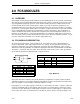
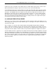
Section 2. FCS Modules 2.0 FCS MODULES 2.1 OVERVIEW The Flexible Control Strategy (FCS) modules are the building blocks of the controller functionality. The modules are presented symbolically with inputs and outputs to eliminate the necessity of learning a programming language; however, each symbol actually represents coded instructions that are executed by the Process Control Station (PCS). The order in which the modules are connected determines the instruction flow executed by the PCS.
FCS 53MC5000 Flexible Control Strategies module can not be connected to the numeric input of another (black output circles connect only to black input diamonds and open output circles connect only to open input diamonds). In the illustration shown, the Logic A module can accept only logical (0/1) input values at A and B. If a 2 were entered into B129, it would cause the logic module to execute the A AND B function on the inputs.
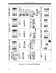
Section 2. FCS Modules Figure 2-1.
FCS 53MC5000 Flexible Control Strategies Figure 2-2.
Section 2. FCS Modules Figure 2-3.
FCS 53MC5000 Flexible Control Strategies 2.4 ASSIGNING WORKSHEET VALUES For single loop controllers the flexible control strategy wirelist datapoint range is from B100 to B172. Two loop and four loop controllers go to B211 and B239 respectivley. This does not include the standard parameter datapoints, e.g., mathematical constants K1-K12, etc., that also affect FCS operation.
Section 2. FCS Modules 2.5 EXECUTING AN FCS WIRELIST The procedure to execute the FCS wirelist is provided in the table that follows: Executing an FCS Wirelist STEP 1 2 3 4 PROCEDURE Enter a 0 into datapoint B000 to stop FCS execution. The MicroMod logo appears on the display screen. Outputs will no longer be updated but remain at their current values.
FCS 53MC5000 Flexible Control Strategies 2.7.1 STATUS DISPLAY 1 LOADER The Status Display 1 (SDT1) Loader module allows operator push button inputs to be acted upon by the FCS function block by mapping SDT1 into the FCS program. Operation of SDT1 is explained in Section 4, Displays, of IB 53MC5000, Revision 2.
Section 2. FCS Modules 2.7.2 CONTACT CLOSURE INPUT LOADER The Contact Closure Input (CCI0-17) Loader module generates a logic level (0/1) L-value output for each connected CCI depending on an applied voltage or the contact condition of its associated terminals (e.g., for CCIs 0 and 1, the minimum open or closed recognition time is 0.05 seconds; 1 V dc maximum = closed contact recognition level; 4 - 24 V dc = open contact recognition level.
FCS 53MC5000 Flexible Control Strategies 2.7.3 ANALOG INPUT LOADER The Analog Input (ANI0-8) Loader module maps the ANI outputs into the FCS program. The output signal is the numeric value in engineering units after all signal conditioning has been applied. The table that follows lists the ANI0-8 outputs and the parameters that affect those outputs. An illustration of the ANI0-8 module follows the table.
Section 2. FCS Modules 2.7.4 EXTENDED MATH A The Extended Math A (Emath A) module executes a selected function on three input variables A, B, and C. The function to be executed by Emath A is selected by entering a function code (FC) from the table below into datapoint B122. Numeric values for parameter constants K1 through K12 can also be entered into their respective datapoints, which may affect the output as determined by the function code selected.
FCS 53MC5000 Flexible Control Strategies 2.7.4.1 PIECEWISE CHARACTERIZER/FUNCTION GENERATOR (FC=15) This FC permits linearization of input signal A or the generation of a function based on the A input. This operation permits the user to specify a piecewise linear approximation (five segments) of the input/output relationship desired. Pieces are specified by six ordered pairs of coordinates (X,Y). Whenever the input exceeds an X-axis end point, the output will be set equal to the Y value of the endpoint.
Section 2. FCS Modules 2.7.4.3 COMPENSATED GAS FLOW (FC = 18 OR FC = 19) Pressure and temperature compensated gas flow equations for both linear and square root flow elements are provided. These equations can be used to compute mass flow or standard volume flow of a gas. The equations handle both perfect and imperfect gases.
FCS 53MC5000 Flexible Control Strategies 2.7.5 MATH A The Math A module executes a selected function on three input variables A, B, and C. The function to be executed by Math A is selected by entering a Function Code (FC) in datapoint B126. Numeric values for parameter constants K1, K2, and K3 can also be entered into their respective datapoints, which may affect the output as determined by the function code selected. The output can be a numeric (C030) and/or a logic (L098) value.
Section 2. FCS Modules 2.7.6 LOGIC A The Logic A module executes a selected function on two input variables A and B to produce an output. Input variables A and B, as well as the output, are all logic values (0/1). The table below lists the input variables; an illustration of the Logic A module follows the table. The function code (FC) to be executed by the Logic A module is selected from the Logic Functions table at the top of the next page and entered into datapoint B129.
FCS 53MC5000 Flexible Control Strategies Logic Functions FC 0 1 2 3 OUTPUT A A OR B A AND B A XOR B Invert output if FC OUTPUT 4 A OR NOT B 5 A AND NOT B 6 J-K LATCH 7 D LATCH FC = FC + 128 Expanded Logic Functions INPUTS FC A 0 0 0 1 0 0 0 1 FC A 1 0 1 1 1 0 1 1 FC A 2 0 2 1 2 0 2 1 FC A 3 0 3 1 3 0 3 1 FC A 4 0 4 1 4 0 4 1 FC A 5 0 5 1 5 0 5 1 FC A 6 0 6 1 6 0 6 1 FC A 7 0 7 1 7 0 7 1 B 1 1 0 0 B 1 1 0 0 B 1 1 0 0 B 1 1 0 0 B 1 1 0 0 B 1 1 0 0 B 1 1 0 0 B 1 1 0 0 OUTPUT A 0 1 0 1 A OR B 1 1 0 1 A AN
Section 2. FCS Modules 2.7.8 PARAMETER LOADER A The Parameter Loader A (PLoad A) module passes a logic value (0/1) from the input B to the output C whenever the A input value is 1. The table that follows lists the input/output variables. An illustration of the Parameter Loader A module follows the table. Inputs WIRELIST SYMBOL B133 B134 A B DATA TYPE L L Output ASSIGNED VALUE WIRELIST SYMBOL B135 C DATA TYPE L ASSIGNED VALUE 2.7.
FCS 53MC5000 Flexible Control Strategies 2.7.10 PARAMETER LOADER C The Parameter Loader C (PLoad C) module passes a numeric value from the input B to the output C whenever the A input value is 1. The table that follows lists the input/output variables. An illustration of the Parameter Loader C module follows the table. Inputs WIRELIST SYMBOL B139 B140 A B DATA TYPE L C Output ASSIGNED VALUE WIRELIST SYMBOL B141 C DATA TYPE C ASSIGNED VALUE 2.7.
Section 2. FCS Modules 2.7.12 PARAMETER LOADER E The Parameter Loader E (PLoad E) module passes a numeric value from the input B to the output C whenever the A input value is 1. The table that follows lists the input/output variables. An illustration of the Parameter Loader E module follows the table.
FCS 53MC5000 Flexible Control Strategies 2.7.13 SETPOINT GENERATOR 0 The Setpoint Generator 0 (SPG 0) module provides a continuous output signal that is derived from one of three sources which are the setpoint track value (STV), the remote setpoint (RSP), or the local setpoint push buttons. The output priority is STV, RSP, and setpoint push buttons. The input variable parameter values also affect the output, as determined by the setpoint selection made.
Section 2. FCS Modules 2.7.14 DEVIATION/ALARM CALCULATION 0 The Deviation/Alarm Calculation 0 (D/C 0) module calculates and loads a Deviation Value (DV), based upon the Setpoint (SP) and the Process Variable (PV). Before the calculation is performed, the setpoint value is conditioned not to exceed the T1 rate of change limit. If the calculated deviation falls within the Control Zone (CZ) value, the deviation is forced to 0.0.
FCS 53MC5000 Flexible Control Strategies 2.7.15 PROPORTIONAL INTEGRAL DERIVATIVE 0 The Proportional Integral Derivative 0 (PID 0) module (which is part of the CON module) performs an interactive PID calculation that duplicates the behavior of conventional analog controllers. Capabilities include external reset, additive feedforward, anti-reset windup, support of all control modes (e.g., P, PI, PD, PID, etc.), and bumpless-balanceless auto transfer.
Section 2. FCS Modules CO0...control output CTC0...control track command DV0...deviation FF0...feed forward IR0...controller span MR0...manual reset OH0...output high limit OL0...output low limit PB0...proportional band PV0...process variable RF0...reset feedback RSW0...reverse switch TD0...rate time TR0...
FCS 53MC5000 Flexible Control Strategies 2.7.16 AUTO/MANUAL SWITCH 0 The Auto/Manual Switch 0 (AMS 0) module provides a continuous output signal that is derived from one of three sources which are the output track value (OTV), control output auto value (CO), or the manual push button value. The output priority is OTV, CO, and output push buttons. The input variable parameter values also affect the output, as determined by the output selection made.
Section 2. FCS Modules 2.7.17 MATH B The Math B module executes a selected function on three input variables A, B, and C. The function to be executed by Math B is selected by entering a Function Code (FC) in datapoint B165. Numeric values for parameter constants K1, K2, and K3 can also be entered into their respective datapoints, which may affect the output as determined by the function code selected. The output can be a numeric (C031) and/or a logic (L095) value.
FCS 53MC5000 Flexible Control Strategies 2.7.18 MATH C The Math C module executes a selected function on three input variables A, B, and C. The function to be executed by Math C is selected by entering a Function Code (FC) in datapoint B169. Numeric values for parameter constants K1, K2, and K3 can also be entered into their respective datapoints, which may affect the output as determined by the function code selected. The output can be a numeric (C032) and/or a logic (L094) value.
Section 2. FCS Modules 2.7.19 LOGIC C The Logic C module executes a selected function on two input variables A and B to produce an output. Input variables A and B, as well as the output, are all logic values (0/1). The table below lists the input variables; an illustration of the Logic C module follows the table. The function code (FC) to be executed by the Logic C module is selected from the Logic Functions table at the bottom of the page and entered into datapoint B172.
FCS 53MC5000 Flexible Control Strategies Expanded Logic Functions INPUTS FC A 0 0 0 1 0 0 0 1 FC A 1 0 1 1 1 0 1 1 FC A 2 0 2 1 2 0 2 1 FC A 3 0 3 1 3 0 3 1 FC A 4 0 4 1 4 0 4 1 FC A 5 0 5 1 5 0 5 1 FC A 6 0 6 1 6 0 6 1 FC A 7 0 7 1 7 0 7 1 B 1 1 0 0 B 1 1 0 0 B 1 1 0 0 B 1 1 0 0 B 1 1 0 0 B 1 1 0 0 B 1 1 0 0 B 1 1 0 0 OUTPUT A 0 1 0 1 A OR B 1 1 0 1 A AND B 0 1 0 0 A XOR B 1 0 0 1 A OR NOT B 0 1 1 1 A AND NOT B 0 0 0 1 J–K LATCH 0 opposite last value unchanged 1 D LATCH 0 1 unchanged unchanged FC 128 1
Section 2. FCS Modules 2.7.20 EXTENDED MATH B The Extended Math B (Emath B) module executes a selected function on three input variables A, B, and C. The function to be executed by Emath B is selected by entering a function code (FC)from the table below into datapoint B176. Numeric values for parameter constants K1 through K12 can also be entered into their respective datapoints, which may affect the output as determined by the function code selected.
FCS 53MC5000 Flexible Control Strategies 2.7.20.1 PIECEWISE CHARACTERIZER/FUNCTION GENERATOR (FC=15) This FC permits linearization of input signal A or the generation of a function based on the A input. This operation permits the user to specify a piecewise linear approximation (five segments) of the input/output relationship desired. Pieces are specified by six ordered pairs of coordinates (X,Y). Whenever the input exceeds an X-axis end point, the output will be set equal to the Y value of the endpoint.
Section 2. FCS Modules 2.7.20.3 COMPENSATED GAS FLOW (FC = 18 OR FC = 19) Pressure and temperature compensated gas flow equations for both linear and square root flow elements are provided. These equations can be used to compute mass flow or standard volume flow of a gas. The equations handle both perfect and imperfect gases.
FCS 53MC5000 Flexible Control Strategies 2.7.21 MATH D The Math D module executes a selected function on three input variables A, B, and C. The function to be executed by Math D is selected by entering a Function Code (FC) in datapoint B180. Numeric values for parameter constants K1, K2, and K3 can also be entered into their respective datapoints, which may affect the output as determined by the function code selected. The output can be a numeric (C034) and/or a logic (L091) value.
Section 2. FCS Modules 2.7.22 LOGIC D The Logic D module executes a selected function on two input variables A and B to produce an output. Input variables A and B, as well as the output, are all logic values (0/1). The table below lists the input variables; an illustration of the Logic D module follows the table. The function code (FC) to be executed by the Logic D module is selected from the Logic Functions table at the top of the next page and entered into datapoint B183.
FCS 53MC5000 Flexible Control Strategies Logic Functions FC 0 1 2 3 OUTPUT FC OUTPUT A 4 A OR NOT B A OR B 5 A AND NOT B A AND B 6 J-K LATCH A XOR B 7 D LATCH Invert output if FC = FC + 128 Expanded Logic Functions INPUTS FC A 0 0 0 1 0 0 0 1 FC A 1 0 1 1 1 0 1 1 FC A 2 0 2 1 2 0 2 1 FC A 3 0 3 1 3 0 3 1 FC A 4 0 4 1 4 0 4 1 FC A 5 0 5 1 5 0 5 1 FC A 6 0 6 1 6 0 6 1 FC A 7 0 7 1 7 0 7 1 B 1 1 0 0 B 1 1 0 0 B 1 1 0 0 B 1 1 0 0 B 1 1 0 0 B 1 1 0 0 B 1 1 0 0 B 1 1 0 0 OUTPUT A 0 1 0 1 A OR B 1 1 0 1 A AND
Section 2. FCS Modules 2.7.24 SETPOINT GENERATOR 1 The Setpoint Generator 1 (SPG 1) module provides a continuous output signal that is derived from one of three sources which are the setpoint track value (STV), the remote setpoint (RSP), or the local setpoint push buttons. The output priority is STV, RSP, and setpoint push buttons. The input variable parameter values also affect the output, as determined by the setpoint selection made. The two tables that follow list the input variables and the parameters.
FCS 53MC5000 Flexible Control Strategies 2.7.25 DEVIATION/ALARM CALCULATION 1 The Deviation/Alarm Calculation 1 (D/C 1) module calculates and loads a Deviation Value (DV), based upon the Setpoint (SP) and the Process Variable (PV). Before the calculation is performed, the setpoint value is conditioned not to exceed the T1 rate of change limit. If the calculated deviation falls within the Control Zone (CZ) value, the deviation is forced to 0.0.
Section 2. FCS Modules 2.7.26 PROPORTIONAL INTEGRAL DERIVATIVE 1 The Proportional Integral Derivative 1 (PID 1) module (which is part of the CON module) performs an interactive PID calculation that duplicates the behavior of conventional analog controllers. Capabilities include external reset, additive feedforward, anti-reset windup, support of all control modes (e.g., P, PI, PD, PID, etc.), and bumpless-balanceless auto transfer.
FCS 53MC5000 Flexible Control Strategies CO1...control output CTC1...control track command DV1...deviation FF1...feed forward IR1...controller span MR1...manual reset OH1...output high limit OL1...output low limit PB1...proportional band PV1...process variable RF1...reset feedback RSW1...reverse switch TD1...rate time TR1...
Section 2. FCS Modules 2.7.27 AUTO/MANUAL SWITCH 1 The Auto/Manual Switch 1 (AMS 1) module provides a continuous output signal that is derived from one of three sources which are the output track value (OTV), control output auto value (CO), or the manual push button value. The output priority is OTV, CO, and output push buttons. The input variable parameter values also affect the output, as determined by the output selection made. The two tables that follow list the input variables and the parameters.
FCS 53MC5000 Flexible Control Strategies 2.7.28 MATH E The Math E module executes a selected function on three input variables A, B, and C. The function to be executed by Math E is selected by entering a Function Code (FC) in datapoint B204. Numeric values for parameter constants K1, K2, and K3 can also be entered into their respective datapoints, which may affect the output as determined by the function code selected. The output can be a numeric (C035) and/or a logic (L088) value.
Section 2. FCS Modules 2.7.29 MATH F The Math F module executes a selected function on three input variables A, B, and C. The function to be executed by Math F is selected by entering a Function Code (FC) in datapoint B208. Numeric values for parameter constants K1, K2, and K3 can also be entered into their respective datapoints, which may affect the output as determined by the function code selected. The output can be a numeric (C036) and/or a logic (L087) value.
FCS 53MC5000 Flexible Control Strategies 2.7.30 LOGIC F The Logic F module executes a selected function on two input variables A and B to produce an output. Input variables A and B, as well as the output, are all logic values (0/1). The table below lists the input variables; an illustration of the Logic F module follows the table. The function code (FC) to be executed by the Logic F module is selected from the Logic Functions table at the bottom of the page and entered into datapoint B211.
Section 2.
FCS 53MC5000 Flexible Control Strategies 2.7.31 SETPOINT GENERATOR 2 The Setpoint Generator 2 (SPG 2) module provides a continuous output signal that is derived from one of three sources which are the setpoint track value (STV), the remote setpoint (RSP), or the local setpoint push buttons. The output priority is STV, RSP, and setpoint push buttons. The input variable parameter values also affect the output, as determined by the setpoint selection made.
Section 2. FCS Modules 2.7.32 CONTROL 2 The Control 2 (CON 2) module combines the operations of Deviation/Alarm Calculation (D/C) and Proportional Integral Derivative (PID) modules. The D/C functionality of the CON 2 module calculates the deviation (DV) value from the setpoint (SP) and the process variable (PV). Before the calculation is performed, the setpoint value is conditioned not to exceed the T1 rate of change limit.
FCS 53MC5000 Flexible Control Strategies ADB2...alarm dead band AIX2...control alarm mode CO2...control output CTC2...control track command CZ2...control zone DV2...deviation FF2...feed forward IR2...controller span MR2...manual reset OH2...output high limit OL2...output low limit PA1-2...alarm A active PA2-2...alarm B active PB2...proportional band PL1-2...alarm limit 1 PL2-2...alarm limit 2 PV2...process variable RF2...reset feedback RSW2...reverse switch SP2...setpoint T1-2...setpoint slew rate TD2...
Section 2. FCS Modules 2.7.33 AUTO/MANUAL SWITCH 2 The Auto/Manual Switch 2 (AMS 2) module provides a continuous output signal that is derived from one of three sources which are the output track value (OTV), control output auto value (CO), or the manual push button value. The output priority is OTV, CO, and output push buttons. The input variable parameter values also affect the output, as determined by the output selection made. The two tables that follow list the input variables and the parameters.
FCS 53MC5000 Flexible Control Strategies 2.7.34 LOGIC G The Logic G module executes a selected function on two input variables A and B to produce an output. Input variables A and B, as well as the output, are all logic values (0/1). The table below lists the input variables; an illustration of the Logic G module follows the table. The function code (FC) to be executed by the Logic G module is selected from the Logic Functions table at the bottom of the page and entered into datapoint B225.
Section 2.
FCS 53MC5000 Flexible Control Strategies 2.7.35 SETPOINT GENERATOR 3 The Setpoint Generator 3 (SPG 3) module provides a continuous output signal that is derived from one of three sources which are the setpoint track value (STV), the remote setpoint (RSP), or the local setpoint push buttons. The output priority is STV, RSP, and setpoint push buttons. The input variable parameter values also affect the output, as determined by the setpoint selection made.
Section 2. FCS Modules 2.7.36 CONTROL 3 The Control 3 (CON 3) module combines the operations of Deviation/Alarm Calculation (D/C) and Proportional Integral Derivative (PID) modules. The D/C functionality of the CON 3 module calculates the deviation (DV) value from the setpoint (SP) and the process variable (PV). Before the calculation is performed, the setpoint value is conditioned not to exceed the T1 rate of change limit.
FCS 53MC5000 Flexible Control Strategies ADB3...alarm dead band AIX3...control alarm mode CO3...control output CTC3...control track command CZ3...control zone DV3...deviation FF3...feed forward IR3...controller span MR3...manual reset OH3...output high limit OL3...output low limit PA1-3...alarm A active PA2-3...alarm B active PB3...proportional band PL1-3...alarm limit 1 PL2-3...alarm limit 2 PV3...process variable RF3...reset feedback RSW3...reverse switch SP3...setpoint T1-3...setpoint slew rate TD3...
Section 2. FCS Modules 2.7.37 AUTO/MANUAL SWITCH 3 The Auto/Manual Switch 3 (AMS 3) module provides a continuous output signal that is derived from one of three sources which are the output track value (OTV), control output auto value (CO), or the manual push button value. The output priority is OTV, CO, and output push buttons. The input variable parameter values also affect the output, as determined by the output selection made. The two tables that follow list the input variables and the parameters.
FCS 53MC5000 Flexible Control Strategies 2.7.38 LOGIC H The Logic H module executes a selected function on two input variables A and B to produce an output. Input variables A and B, as well as the output, are all logic values (0/1). The table below lists the input variables; an illustration of the Logic H module follows the table. The function code (FC) to be executed by the Logic H module is selected from the Logic Functions table at the bottom of the page and entered into datapoint B239.
Section 2.
FCS 53MC5000 Flexible Control Strategies 2.7.39 ANALOG OUTPUT LOADER The Analog Output (ANO0-4) Loader module has parameters which allow an FCS signal to be scaled to the proper units before it is supplied to an analog output from the 53MC5000 Process Control Station (PCS).
Section 2. FCS Modules 2.7.40 CONTACT CLOSURE OUTPUT LOADER The Contact Closure Output (CCO0-5) Loader module responds to the logic level L-value (0/1) inputs for each CCO0-5. Normally, each CCO response is closed for a 1 input and open for a 0 input; however, this action can be reversed with the invert parameter (OINV) listed in the table. The table that follows lists the CCO0-5 L-value inputs with their respective invert parameters that affect CCO response.
FCS 53MC5000 Flexible Control Strategies 2.7.41 STATUS DISPLAY 0 LOADER The Status Display 0 (SDT0A-0H) Loader module allows FCS logic signals to be tied to SDT0 so that configured messages can be displayed that reflect conditions of PCS operation. The ten character display message (LABLE) is configured with attributes (e.g., flashing, reverse video, etc.) using the SDT0 parameters listed in the table that follows.
Section 3. FCS Wirelist Examples 3.0 FCS WIRELIST EXAMPLES 3.1 OVERVIEW This section provides four Flexible Control Strategy wirelist examples. Each example has a brief functional description of the control strategy, an illustration of the connected modules, and completed wirelist worksheets. Only those worksheets applicable to the control strategy are provided with each example and not the entire worksheet set of Appendix B.
FCS 53MC5000 Flexible Control Strategies 3.2 EXAMPLE 1 - LOGICAL ONESHOT A logical oneshot can be used to toggle a Contact Closure Output (CCO) or reset a totalizer. As shown in Figure 3-1, a oneshot pulsed output can be generated from a Logic module. Generating a pulsed output from a Logic module requires comparing a logical input from the previous scan with a second logical input from the current scan.
Section 3. FCS Wirelist Examples The wirelist is provided in Table 3-1, which is an example worksheet of this control strategy. Wirelist datapoint values and associated module parameter datapoint values are shown in bold typeface. Table 3-1.
FCS 53MC5000 Flexible Control Strategies Table 3-1. Logical Oneshot Wirelist FCS WORKSHEET Oneshot EXTENDED MATH A ONE LOOP W/L DEFLT VALUE B119 255 C PAGE 2 OF 2 COMMENTS: Output datapoints for this module are C029, L099. NAME A B120 254 C B B121 253 C C B122 000 FC MATH A ONE LOOP K1 C354 0 K2 C355 0 K12 C365 0 K11 C364 0 K10 C363 0 K9 C362 0 K8 C361 0 K3 C356 0 K4 C357 0 K5 C358 0 K6 C359 0 K7 C360 0 COMMENTS: Output datapoints for this module are C030, L098.
Section 3. FCS Wirelist Examples 3.3 EXAMPLE 2 - LOGIC OPERATED SWITCH Signal switching is built into the Setpoint Generator and Auto/Manual Selector modules, and conditional signal switching can be affected using the Math modules. Figure 3-2 below illustrates an independent logic operated switch that uses two Parameter Loader modules and a Logic module.
FCS 53MC5000 Flexible Control Strategies Table 3-2. Logic Operated Switch - CCI0 = 1 Step 5 6 Module Datapoint C005 ANO’s Input(s) C005 = B144 (ANI1) B100 = C005 (ANI1). Output(s) Comments ANO0 = B100 = ANI1. If CCI0 = 0, the following event sequence occurs as described in Table 3-3: Table 3-3. Logic Operated Switch - CCI0 = 0 Step 1 2 Param D 3 Logic A 4 Param E 5 Datapoint C005 ANO’s 6 3-6 Module Input(s) ANI B143 = C021 (ANI1) and B142 = L000, which is 0 and inhibits the output.
Section 3. FCS Wirelist Examples The wirelist is provided in Table 3-4, which is an example worksheet of this control strategy. Wirelist datapoint values and associated module parameter datapoint values are shown in bold typeface. Table 3-4.
FCS 53MC5000 Flexible Control Strategies Table 3-4.
FCS 53MC5000 Flexible Control Strategies Table 3-4. Logic Operated Switch Wirelist FCS WORKSHEET Switch EXTENDED MATH A ONE LOOP W/L DEFLT VALUE B119 255 C PAGE 3 OF 4 COMMENTS: Output datapoints for this module are C029, L099. NAME A B120 254 C B B121 253 C C B122 000 FC MATH A ONE LOOP K1 C354 0 K2 C355 0 K12 C365 0 K11 C364 0 K10 C363 0 K9 C362 0 K8 C361 0 K3 C356 0 K4 C357 0 K5 C358 0 K6 C359 0 K7 C360 0 COMMENTS: Output datapoints for this module are C030, L098.
Section 3. FCS Wirelist Examples Table 3-4.
Section 3. FCS Wirelist Examples 3.4 EXAMPLE 3 - HIGH/LOW SELECTOR WITH RE-TRANSMISSION Under normal operation, the Setpoint Generator module is used to select an operating setpoint from one of three sources: the setpoint track value, the remote setpoint, or the local setpoint push buttons. As shown in Figure 3-3 below, this control strategy uses Setpoint Generator 0 to select an output from signal values at ANI0 or ANI1.
FCS 53MC5000 Flexible Control Strategies If ANI0 is greater than or equal to ANI1, the following event sequence occurs as described in Table 3-5: Table 3-5. High/Low Selector - ANI0 ≥ ANI1 Step 1 Module 2 Math A 3 Logic A 4 SP Gen 0 5 Logic B 6 Param C 7 Param D 8 9 Datapoint C005 Math B 10 ANO’s 3-12 Input(s) ANI ANI0 (B123) and ANI1 (B124). B127 = 1 and B128 = 1.
Section 3. FCS Wirelist Examples If ANI0 is less than ANI1, the following event sequence occurs as described in Table 3-6: Table 3-6. High/Low Selector - ANI0 < ANI1 Step 1 EX3 Module Input(s) ANI 2 Math A ANI0 (B123) and ANI1 (B124). B127 = 1 and B128 = 1. 3 Logic A 4 SP Gen 0 5 Logic B 6 Param C B139 = L104 (0 from step 4 output), whic inhibits Param C output. 7 Param D 8 9 Datapoint C005 Math B 10 ANO’s B142 = L096 (1 from step 5 output), which enables Param D output.
FCS 53MC5000 Flexible Control Strategies The wirelist is provided in Table 3-7, which is an example worksheet of this control strategy. Wirelist datapoint values and associated module parameter datapoint values are shown in bold typeface. The parameter datapoint values used, such as the Math B K1 value (C079) should be configured as required. Table 3-7.
Section 3. FCS Wirelist Examples Table 3-7.
FCS 53MC5000 Flexible Control Strategies Table 3-7. High/Low Selector Wirelist FCS WORKSHEET Selector EXTENDED MATH A ONE LOOP W/L DEFLT VALUE B119 255 C COMMENTS: Output datapoints for this module are C029, L099.
Section 3. FCS Wirelist Examples Table 3-7.
FCS 53MC5000 Flexible Control Strategies Table 3-7. High/Low Selector Wirelist FCS WORKSHEET Selector DEVIATION/ALARM CALC 0 ONE LOOP W/L DEFLT VALUE B152 100 C B153 101 C PID 0 ONE LOOP W/L DEFLT VALUE B154 121 C PAGE 5 OF 5 COMMENTS: Output datapoints for this module are C119, C121, L110, L111. NAME PV0 T1-0 C117 0 CZ0 C114 0 PL1-0 C103 100 PL2-0 C104 0 ADB0 C105 2 AIX0 B335 1 SP0 COMMENTS: Output datapoint for this module is C123.
Section 3. FCS Wirelist Examples 3.5 EXAMPLE 4 - MASTER RATIO CONTROLLER As shown in Figure 3-4 below, this control strategy accepts two inputs: the Controlled Variable (CV) at ANI0 and the Remote Setpoint (RSP) or Wild Variable at ANI1. The CV passes through the Emath A module unaffected (FC=0) before being applied to the input of the Deviation 0 module. The RSP is ratio augmented by the FC = 1 [(K1xA)+K2] of the Math A module before being applied to Setpoint Generator 0.
FCS 53MC5000 Flexible Control Strategies The wirelist is provided in Table 3-8, which is an example worksheet of this control strategy. Wirelist datapoint values and associated module parameter datapoint values are shown in bold typeface. The parameter datapoint values used, such as the ANI0 Span (C256) and Zero (C276), are for illustrative purposes and can be altered as required. Miscellaneous datapoints, which include the display selection datapoints, are listed last in the table.
FCS 53MC5000 Flexible Control Strategies Table 3-8.
FCS 53MC5000 Flexible Control Strategies Table 3-8. Master Ratio Controller Wirelist FCS WORKSHEET Ratio Controller EXTENDED MATH A ONE LOOP W/L DEFLT VALUE B119 255 C PAGE 3 OF 6 COMMENTS: Output datapoints for this module are C029, L099.
Section 3. FCS Wirelist Examples Table 3-8.
FCS 53MC5000 Flexible Control Strategies Table 3-8. Master Ratio Controller Wirelist DEVIATION/ALARM CALC 0 ONE LOOP W/L DEFLT VALUE B152 100 C COMMENTS: Output datapoints for this module are C119, C121, L110, L111. NAME PV0 029 B153 101 C T1-0 C117 0 CZ0 C114 0 PL1-0 C103 100 PL2-0 C104 0 ADB0 C105 2 AIX0 B335 1 SP0 101 PID 0 ONE LOOP W/L DEFLT VALUE B154 121 C COMMENTS: Output datapoint for this module is C123.
Section 3. FCS Wirelist Examples Table 3-8. Master Ratio Controller Wirelist FCS WORKSHEET Ratio Controller PAGE 6 OF 6 MISCELLANEOUS DATAPOINTS Datapoint Value Entered A000 FCS95345 CON0 Title A001 e.g., GPM CON0 Engineering Units A092 TOT95345 Totalizer 0 Title A093 e.g., 10XGPM Totalizer 0 Engineering Units F216 H000 ANI0 PV is input to Totalizer 0 C318 0.
Appendix A. Control Strategy Wirelists APPENDIX A: CONTROL STRATEGY WIRELISTS A.1 STANDARD CONTROL STRATEGIES The wirelists for the ten control strategies of the 53MC5000 Process Control Station (PCS) are provided in this section. The resident control strategies of a PCS are option dependent: a one loop PCS has 5 control strategies, CS1 - CS5; a two loop PCS has 8 control strategies, CS1 - CS22; and a four loop PCS has 10 control strategies, CS1 - CS41.
FCS 53MC5000 Flexible Control Strategies A.1.1 CS1 - SINGLE-LOOP PID CONTROLLER The PID controller is designed to fulfill the requirements of a majority of process applications. It is used in conjunction with other devices in a standard feedback control loop to automatically control a process variable (PV) at a predetermined setpoint (SP). The proportional, integral, and derivative (PID) terms can be activated as needed. The control scheme is shown in block diagram form in Figure A–1.
Appendix A. Control Strategy Wirelists Figure A-1.
FCS 53MC5000 Flexible Control Strategies Table A-1.
Appendix A. Control Strategy Wirelists Table A-1.
FCS 53MC5000 Flexible Control Strategies Table A-1.
Appendix A. Control Strategy Wirelists Table A-1.
FCS 53MC5000 Flexible Control Strategies Table A-1.
Appendix A. Control Strategy Wirelists Table A-1.
FCS 53MC5000 Flexible Control Strategies A.1.2 CS2 - ANALOG BACKUP CONTROLLER The analog backup controller is used in operations where a remote computer normally controls the final element directly. In this arrangement the controller acts as a control signal selector and as an automatic backup. As a backup, the controller will assume control of the process in the event of an indicated computer failure. Loading CS2 initializes the ANI3 engineering span to 100.0, the CCO0 invert to 1, and C078 to 100.0.
Appendix A. Control Strategy Wirelists Figure A-2.
FCS 53MC5000 Flexible Control Strategies Table A-2.
Appendix A. Control Strategy Wirelists Table A-2.
FCS 53MC5000 Flexible Control Strategies Table A-2.
Appendix A. Control Strategy Wirelists Table A-2.
FCS 53MC5000 Flexible Control Strategies Table A-2.
Appendix A. Control Strategy Wirelists Table A-2.
FCS 53MC5000 Flexible Control Strategy A.1.3 CS3 - RATIO CONTROLLER The ratio PID controller is used where a controlled variable must automatically be maintained in definite proportion to an uncontrolled or wild variable. Loading CS3 initializes the ANI1 engineering span to 100.0, CON0 display mode to 3, CON0 setpoint mode to 1, and C081 to 1.0. The control scheme is shown in block diagram form in Figure A3.
Appendix A. Control Strategy Wirelists Figure A-3.
FCS 53MC5000 Flexible Control Strategies Table A-3.
Appendix A. Control Strategy Wirelists Table A-3.
FCS 53MC5000 Flexible Control Strategies Table A-3.
Appendix A. Control Strategy Wirelists Table A-3.
FCS 53MC5000 Flexible Control Strategies Table A-3.
Appendix A. Control Strategy Wirelists Table A-3.
FCS 53MC5000 Flexible Control Strategies A.1.4 CS4 - AUTOMATIC/MANUAL STATION The automatic/manual station configures the controller into a conventional single station automatic/manual selector with manual loading. Loading CS4 initializes the CON0 display mode to 4. The Auto/Manual Station is shown in block diagram form in Figure A–4. Also provided is Table A-4, which is a worksheet that shows the CS4 wirelist connections; wirelist datapoints not connected are left at default.
Appendix A. Control Strategy Wirelists Figure A-4.
FCS 53MC5000 Flexible Control Strategies Table A-4.
Appendix A. Control Strategy Wirelists Table A-4.
FCS 53MC5000 Flexible Control Strategies Table A-4.
Appendix A. Control Strategy Wirelists Table A-4.
FCS 53MC5000 Flexible Control Strategies Table A-4.
Appendix A. Control Strategy Wirelists Table A-4.
FCS 53MC5000 Flexible Control Strategies A.1.5 CS5 - RATIO AUTOMATIC/MANUAL STATION The ratio automatic/manual station configures the controller into a ratio automatic/manual selector with manual loading. Loading CS5 generates the CON0 display mode to 5, CON0 setpoint mode to 1, and the ANI1 engineering span to 100.0. The Ratio Auto/Manual Station is shown in block diagram form in Figure A5.
Appendix A. Control Strategy Wirelists Figure A-5.
FCS 53MC5000 Flexible Control Strategies Table A-5.
Appendix A. Control Strategy Wirelists Table A-5.
FCS 53MC5000 Flexible Control Strategies Table A-5.
Appendix A. Control Strategy Wirelists Table A-5.
FCS 53MC5000 Flexible Control Strategies Table A-5.
Appendix A. Control Strategy Wirelists Table A-5.
FCS 53MC5000 Flexible Control Strategies A.1.6 CS20 - TWO-LOOP CONTROLLER The two-loop controller provides two standard PID controllers in a single cabinet enclosure. Loading CS20 initializes the ANI1 engineering span to 100.0 and the display list sequence to incorporate a second display group (CON1). The control scheme is shown in block diagram form in Figure A-6.
Appendix A. Control Strategy Wirelists Figure A-6.
FCS 53MC5000 Flexible Control Strategies Table A-6.
Appendix A. Control Strategy Wirelists Table A-6.
FCS 53MC5000 Flexible Control Strategies Table A-6.
Appendix A. Control Strategy Wirelists Table A-6.
FCS 53MC5000 Flexible Control Strategies Table A-6.
Appendix A. Control Strategy Wirelists Table A-6.
FCS 53MC5000 Flexible Control Strategies Table A-6.
Appendix A. Control Strategy Wirelists Table A-6.
FCS 53MC5000 Flexible Control Strategies A.1.7 CS21 - TWO-LOOP CASCADE CONTROLLER The two-loop cascade controller consists of two standard PID control loops, arranged in a cascade setup whereby the output of the primary controller, based on its setpoint and process variable, becomes the setpoint for the secondary controller. Loading CS21 initializes the ANI2 engineering span to 100.0, C088 to 1.0, C089 to 1.0, and the display list sequence to incorporate a second display group (CON1).
Appendix A. Control Strategy Wirelists Figure A-7.
FCS 53MC5000 Flexible Control Strategies Table A-7.
Appendix A. Control Strategy Wirelists Table A-7.
FCS 53MC5000 Flexible Control Strategies Table A-7.
Appendix A. Control Strategy Wirelists Table A-7.
FCS 53MC5000 Flexible Control Strategies Table A-7.
Appendix A. Control Strategy Wirelists Table A-7.
FCS 53MC5000 Flexible Control Strategies Table A-7.
Appendix A. Control Strategy Wirelists Table A-7.
FCS 53MC5000 Flexible Control Strategies A.1.8 CS22 - TWO-LOOP OVERRIDE CONTROLLER The two-loop override controller has two standard PID control loops. Override control is used when two interdependent variables are being controlled with a single final element and neither variable may exceed a safe limit. Whichever variable is changing in the undesirable direction must be the loop maintaining control of the final element.
Appendix A. Control Strategy Wirelists Figure A-8.
FCS 53MC5000 Flexible Control Strategies Table A-8.
Appendix A. Control Strategy Wirelists Table A-8.
FCS 53MC5000 Flexible Control Strategies Table A-8.
Appendix A. Control Strategy Wirelists Table A-8.
FCS 53MC5000 Flexible Control Strategies Table A-8.
Appendix A. Control Strategy Wirelists Table A-8.
FCS 53MC5000 Flexible Control Strategies Table A-6.
Appendix A. Control Strategy Wirelists Table A-6.
FCS 53MC5000 Flexible Control Strategies A.1.9 CS40 - DUAL TWO-LOOP CASCADE CONTROLLER The dual two-loop cascade controller consists of four standard PID control loops, arranged as two cascade pairs, with a primary and a related secondary controller. Loading CS40 initializes the ANI1–3 engineering spans to 100.0, C076 and C085 to 1.0, C077 and C086 to -1.0, and the four loop control list sequence. The control scheme is shown in block diagram form in Figure A-9.
Appendix A. Control Strategy Wirelists Figure A-9.
FCS 53MC5000 Flexible Control Strategies Table A-9.
Appendix A. Control Strategy Wirelists Table A-9.
FCS 53MC5000 Flexible Control Strategies Table A-9.
Appendix A. Control Strategy Wirelists Table A-9.
FCS 53MC5000 Flexible Control Strategies Table A-9.
Appendix A. Control Strategy Wirelists Table A-9.
FCS 53MC5000 Flexible Control Strategies Table A-9.
Appendix A. Control Strategy Wirelists Table A-9.
FCS 53MC5000 Flexible Control Strategies Table A-9.
Appendix A. Control Strategy Wirelists A.1.10 CS41 - FOUR-LOOP CONTROLLER The four-loop controller provides four independent PID controllers. Loading CS41 initializes the ANI1–7 engineering spans to 100.0, and the display list is modified to the four-loop sequence. The control scheme is shown in block diagram form in Figure A–10. Also provided is Table A-10, which is a worksheet that shows the CS41 wirelist connections; wirelist datapoints not connected are left at default.
FCS 53MC5000 Flexible Control Strategies Figure A-10.
FCS 53MC5000 Flexible Control Strategies Table A-10.
Appendix A. Control Strategy Wirelists Table A-10.
FCS 53MC5000 Flexible Control Strategies Table A-10.
Appendix A. Control Strategy Wirelists Table A-10.
FCS 53MC5000 Flexible Control Strategies Table A-10.
Appendix A. Control Strategy Wirelists Table A-10.
FCS 53MC5000 Flexible Control Strategies Table A-10.
Appendix A. Control Strategy Wirelists Table A-10.
FCS 53MC5000 Flexible Control Strategies Table A-10.
Appendix A. Control Strategy Wirelists This page intentionally left blank.
Appendix B. Master Worksheets APPENDIX B: MASTER WORKSHEETS This appendix contains blank master worksheets for photocopying. Entries are not made on the master worksheets. FCS wirelist entries are entered on the applicable photocopied worksheets, as determined by the FCS modules used to build the control strategy (it is not necessary to make photocopies of all of the master worksheets to build a Flexible Control Strategy).
FCS 53MC5000 Flexible Control Strategies Applicable Loop Number 1, 2, 4 2 2 2 2 4 4 4 4 4 4 4 4 B-2 Datapoint Range B197 B201 B205 B209 B212 B216 B219 B223 B226 B230 B233 B237 - B200 B204 B208 B211 B215 B218 B222 B225 B229 B232 B236 B239 FCS Module Auto/Manual Switch 1 Math E Math F Logic F Setpoint Generator 2 Control 2 Auto/Manual Switch 2 Logic G Setpoint Generator 3 Control 3 Auto/Manual Switch 3 Logic H ENTRIES
FCS 53MC5000 Flexible Control Strategies FCS WORKSHEET TITLE: ORIGINATOR: ANI LOAD INPUT ONE, TWO, AND FOUR LOOPS W/L N/A DEFLT N/A VALUE N/A NAME ANI0 N/A N/A N/A N/A N/A N/A PAGE ___ OF ___ DATE: REV: COMMENTS: SPAN0 C256 100 ZERO0 C276 0 DFILT0 B269 3 NOBIAS0 L416 0 SQRT0 L440 0 OUTPUT0 C020 0 ANI1 SPAN1 C257 0 ZERO1 C277 0 DFILT1 B270 3 NOBIAS1 L417 0 SQRT1 L441 0 OUTPUT1 C021 0 N/A ANI2 SPAN2 C258 0 ZERO2 C278 0 DFILT2 B271 3 NOBIAS2 L418 0 SQRT2 L442 0 OUTPUT2 C022 0
Appendix B.
FCS 53MC5000 Flexible Control Strategies FCS WORKSHEET SDT1 LOAD INPUT ONE, TWO, AND FOUR LOOPS W/L N/A DEFLT N/A VALUE N/A NAME SDT1A N/A N/A N/A N/A N/A N/A PAGE ___ OF ___ COMMENTS: STA1 NAME1 A064 ALARMI SMA1 MODE0 L360 0 SAA1 AEN0 L376 0 SKA1 AKN0 L392 0 SDA1 MODDIS0 L328 0 OUTPUT0 L103 0 SDT1B STB1 NAME2 A065 ALARMJ SMB1 MODE1 L361 0 SAB1 AEN1 L377 0 SKB1 AKN1 L393 0 SDB1 MODDIS1 L329 0 OUTPUT1 L102 0 N/A SDT1C STC1 NAME3 A066 ALARMK SMC1 MODE2 L362 0 SAC1 AEN2 L378 0 SK
FCS 53MC5000 Flexible Control Strategies FCS WORKSHEET ANO LOAD OUTPUT ONE, TWO, AND FOUR LOOPS W/L DEFLT VALUE B100 000 C NAME ANO0 B101 001 C B102 002 B103 B104 PAGE ___ OF ___ COMMENTS: ANO = (INPUT x SCALER) + BIAS OZBASE0 L472 0 SCALER0 C037 0/1 BIAS0 C038 0/1 ANO1 OZBASE1 L473 0 SCALER1 C039 0/1 BIAS1 C040 0/1 C ANO2 OZBASE2 L474 0 SCALER2 C041 0/1 BIAS2 C042 0/1 003 C ANO3 OZBASE3 L475 0 SCALER3 C043 0/1 BIAS3 C044 0/1 004 C ANO4 OZBASE4 L476 0 SCALER4 C045 0/1 BIAS
Appendix B.
FCS 53MC5000 Flexible Control Strategies FCS WORKSHEET EXTENDED MATH A ONE LOOP W/L DEFLT VALUE B119 255 C COMMENTS: Output datapoints for this module are C029, L099. NAME A B120 254 C B B121 253 C C B122 000 FC MATH A ONE LOOP W/L DEFLT VALUE B123 076 C C B B125 078 C C B126 000 097 FC B129 000 L 096 B132 000 K9 C362 0 K8 C361 0 K3 C356 0 K4 C357 0 K5 C358 0 K6 C359 0 K7 C360 0 K1 C076 0 K2 C077 0 K3 C078 0 COMMENTS: Output datapoint for this module is L097.
Appendix B.
FCS 53MC5000 Flexible Control Strategies FCS WORKSHEET B152 100 C PV0 B153 101 C SP0 PAGE ___ OF ___ T1-0 C117 0 PID 0 ONE LOOP W/L DEFLT VALUE B154 121 C C FF0 B156 123 L CTC0 B157 111 C RF0 AUTO/MANUAL SWITCH 0 ONE LOOP W/L DEFLT VALUE NAME B158 114 L AE0 B159 117 L SWOVT0 B160 129 C OTV0 B161 123 C CO0 AIX0 B335 1 OH0 C109 100 OL0 C110 0 IR0 C155 0 PB0 C106 100 TR0 C107 0 PV0 C100 0 RSW0 L106 1 TD0 C108 0 MR0 C111 50 COMMENTS: Output datapoints for this module ar
Appendix B. Master Worksheets FCS WORKSHEET B170 093 L A B171 093 L B B172 000 FC EXTENDED MATH B TWO LOOP W/L DEFLT VALUE B173 255 C COMMENTS: Output datapoints for this module are C033, L092.
FCS 53MC5000 Flexible Control Strategies FCS WORKSHEET SETPOINT GENERATOR 1 TWO LOOP W/L DEFLT VALUE NAME B187 164 C STV1 B188 140 L SWSPT1 B189 156 C RSP1 B190 139 L RE1 DEVIATION/ALARM CALC 1 TWO LOOP W/L DEFLT VALUE NAME B191 136 C PV1 B192 137 C PAGE ___ OF ___ COMMENTS: Output datapoints for this module are C137, L128, L132.
Appendix B. Master Worksheets FCS WORKSHEET B205 091 C A B206 092 C B B207 093 C C B208 000 FC LOGIC F TWO LOOP W/L DEFLT VALUE B209 086 L B210 086 B211 000 L K2 C092 0 K3 C093 0 NAME A B FC B213 164 L SWSPT2 B214 192 C RSP2 B215 163 L RE2 CONTROL 2 FOUR LOOP W/L DEFLT VALUE B216 172 C COMMENTS: Output datapoints for this module are C173, L152, L156.
FCS 53MC5000 Flexible Control Strategies FCS WORKSHEET B223 085 L A B224 085 L B B225 000 FC SETPOINT GENERATOR 3 FOUR LOOP W/L DEFLT VALUE NAME B226 236 C STV3 B227 188 L SWSPT3 B228 228 C RSP3 B229 187 L RE3 CONTROL 3 FOUR LOOP W/L DEFLT VALUE B230 208 C NAME PV3 209 C SP3 B232 230 C FF3 AUTO/MANUAL SWITCH 3 FOUR LOOP W/L DEFLT VALUE NAME B233 186 L AE3 B234 189 L SWOVT3 B235 237 C OTV3 B236 231 C CO3 LOGIC H FOUR LOOP W/L DEFLT VALUE B237 084 L 084 B239 000
Appendix B.
FCS 53MC5000 Flexible Control Strategies FCS WORKSHEET PAGE ___ OF ___ MISCELLANEOUS DATAPOINTS Datapoint B-16 Value Entered Title/Comments MISCPT
The Company’s policy is one of continuous product improvement and the right is reserved to modify the information contained herein without notice, or to make engineering refinements that may not be reflected in this bulletin. Micromod Automation assumes no responsibility for errors that may appear in this manual. © 2004 MicroMod Automation, Inc. Printed in USA MicroMod Automation, Inc. 75 Town Center Drive Rochester, NY USA 14623 Tel. 585-321-9200 Fax 585-321-9291 www.micromodautomation.