
Owner's manual

53IT5100B Indicator/Totalizer
INSTRUCTION MANUAL
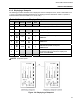
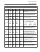
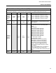
Table 4-7. Alarm Module
Purpose: The primary purpose of this module is to set the instrument’s Alarm Index mode, Alarm
Limits 1 & 2, and Alarm Dead Band.
Title Symbol CCO Data-point Default Attribute
Alarm
Index
AIX0
AIX1
AIX2
AIX3
ALRM
0
ALRM
1
ALRM
2
ALRM
3
B335
B340
B345
B350
1
1
1
1
This parameter defines the Alarm Active (PA1 &
PA2) interpretation of the two Alarm Limits (PL1
& PL2). It is entered into the datapoint as an
index value (0-5 ) as follows (n = 0-3 and
correlates with ALRM0 through ALRM3):
0 PA1n: high when PV> PL1n
PA2n: low when PV< PL2n
1 None
2 PA1n: high when PV> PL1n
PA2n: not affected
3 PA1n: not affected
PA2n: low when PV< PL1n
4 PA1n: high when PV> PL1n
PA2n: hi-hi when PV> PL2n
5 PA1n: low when PV< PL1n
PA2n: lo-lo when PV< PL2n
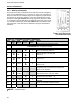
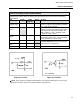
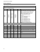
Examples are provided as follows:
Alarm Examples:
B335 PV PL1
(C103)
PL2 (C104) Alarm Notes
0 >60 60 high Alarm Llimit 1 is set for 60: PV > 60 = high Alarm.
0 <40 40 low Alarm Limit 2 is set for 40: PV < 40 = low Alarm.
2 >60 60 high Alarm Limit 1 is set for 60: PV > 60 = high Alarm.
2 <40 40 N/A Alarm Limit 2 is set for 40: PV < 40 = no alarm.
3 >60 60 N/A Alarm Limit 1 is set for 60: PV > 60 = no alarm.
3 <40 40 Low
low Alarm Limit 2 is set for 40: PV < 40 = low
Alarm.
4 >60 60 high Alarm Limit 1 is set for 60: PV > 60 = high Alarm.
4 <70 70 hi-hi Alarm Limit 2 is set for 70: PV > 70 = hi-hi Alarm.
5 >40 40 low Alarm Limit 1 is set for 40: PV < 40 = low Alarm.
5 <30 30 low-low Alarm Limit 2 is set for 30: PV < 30 = lo-lo Alarm.
36