
Owner's manual

53IT5100B Indicator/Totalizer
INSTRUCTION MANUAL
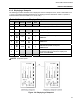
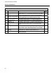
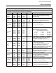
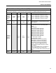
Table 4-2. Database Modules
Item Title Purpose See
Table
1 Analog Input Module This module is used to configure the voltage input
characteristics (e.g., input voltage range) and how the input
signal is interpreted (linear or square root representation).
4-3
2
Analog Output Module
The primary purpose of this module is to set the 0 - 20 mA
output signal relative to the displayed percent output.
4-4
3 Contact Input Module This module allows the action of the CCIs to be reversed
(normally a closed contact = 1, but can be change to = 0).
4-5
4 Contact Output
Module
This module allows the action of a CCOs to be reversed
(normally a closed contact = 1, but can be changed to = 0).
4-6
5 Alarm Module The primary purpose of this module is to set the instrument’s
Alarm Index mode, Alarm Limits 1 & 2, and Alarm Dead
Band.
4-7
6 Totalizer Module The totalizers provide the sum of each analog input (ANI0-3).
This module is used to set input scaling factors, rollover and
dropout values, and to define display tags for each totalizer.
4-8
7 Communication
Module
This module is used to configure the Datalink port
parameters (e.g., baud rate, parity selection, etc.).
4-9
8 System Module This module is used to set the instrument tag name and the
display brightness.
4-10
30