
Manual

5.6 PARTS LIST
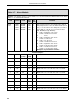
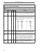
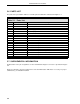
The parts list is provided in Table 5-1 and the parts breakdown is illustrated in Figure 5-1.
Table 5-1. Parts List
Key Part Number Description
1 612B395U02 Case
2 686B689U02 Main Printed Circuit Board
3 164B130U03 Power Supply - 120/220/240 V ac, 50/60 Hz
3 164B130U04 Power Supply - 24 V dc
4 698B179U07/U08 Front Display
5 686B598U01 Rear Terminal Board
6 677B942U01 Cable - Display to Main PCB
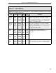
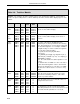
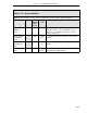
173D109U03 U.S. Power Cord - 120 V ac, 50/60 Hz
355J093U01 Trim Collar for Single Case
614B836U01 Trim Collar and Spacer for Two Cases
614B836U02 Trim Collar and Spacer for Three Cases
614B836U03 Trim Collar and Spacer for Four Cases
614B836U04 Trim Collar and Spacer for Five Cases
614B836U05 Trim Collar and Spacer for Six Cases
614B836U06 Trim Collar and Spacer for Seven Cases
614B836U07 Trim Collar and Spacer for Eight Cases
614B836U08 Trim Collar and Spacer for Nine Cases
614B836U09 Trim Collar and Spacer for Ten Cases
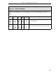
614B762U02 Kit of Three Plates for 3 X 6 Instrument Panel Cutout
5.7 SUPPLEMENTAL INFORMATION
An illustration of the pin assignments for the Hand Held Configurer connector is provided in Figure
5-2.
Figure 5-3 illustrates the pin assignments for the Communication ITB that is necessary for proper
termination(s) of a Datalink network.
53IT5100 Indicator/Totalizer
5-4