
Manual
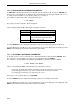
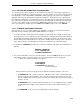
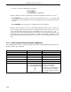
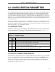
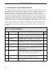
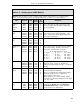
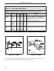
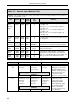
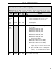

Table 4-6. Contact Output Module (CCO)
Purpose:
This module allows the action of the CCOs to be reversed (normally a closed contact =
1, but can be changed to = 0) and is used to select the signal or condition that activates the CCO.
Title Symbol CCO Data-
point
De-
fault
Attribute
Contact
Output
(Display
Only)
CCO0
CCO1
CCO0
CCO1
L024
L025
0
0
If CCO =
0
and OINV =
0
, then it is open.
If CCO =
0
and OINV =
1
, then it is closed.
If CCO =
1
and OINV =
0
, then it is closed.
If CCO =
1
and OINV =
1
, then it is open.
Contact
Output
Invert
OINV0
OINV1
CCO0
CCO1
L288
L289
0
0
As shown above, it reverses the action of the
CCO datapoint.
Control
Contact
Output
Source
CCO0
CCO1
B101
B102
110
134
This parameter selects the signal or condition
that activates the CCO. The routing index values
are as follows:
110
Channel 0 Alarm A (PA10).
111
Channel 0 Alarm B (PA20).
134
Channel 1 Alarm A (PA11).
135
Channel 1 Alarm B (PA21).
158
Channel 2 Alarm A (PA12).
159
Channel 2 Alarm B (PA22).
182
Channel 3 Alarm A (PA13).
183
Channel 3 Alarm B (PA23).
0
Contact Input 0 (CCI0).
1
Contact Input 1 (CCI1).
224
Totalizer 0 Rollover Pulse (TMP0).
225
Totalizer 1 Rollover Pulse (TMP1).
226
Totalizer 2 Rollover Pulse (TMP2).
227
Totalizer 3 Rollover Pulse (TMP3).
65
Horn - latches the
OR
function of all
alarms (8 process alarm bits and 2 contact
input alarms).
99
Non-latched
OR
function of all alarms (8
process alarm bits and 2 contact input
alarms). It is cleared when the last alarm
goes away.
Tag
Name
COTAG0
COTAG1
CCO0
CCO1
A280
A281
CCO-0
CCO-1
It is an assignable 10 character name for the
contact control output.
Section 4. Configuration Parameters
4-7