
Manual
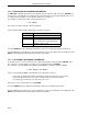
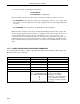
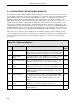
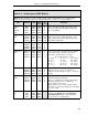
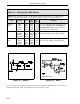
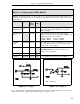
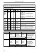
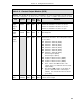

Table 4-3. Analog Input (ANI) Module
Purpose:
This module is used to configure input voltage characteristics (e.g., input voltage
range), and how the input signals are interpreted (linear or square root representation).
Title Symbol ANI Data-
point
De-
fault
Attribute
Calibrate
Span
CIS0
CIS1
CIS2
CIS3
ANI0
ANI1
ANI2
ANI3
C296
C297
C298
C299
This is the calibration span adjustment. This
parameter
is factory set
and
should not
need adjustment
under normal operation.
See Section 5.3 for adjustment.
Tag Name AITAG0
AITAG1
AITAG2
AITAG3
ANI0
ANI1
ANI2
ANI3
A224
A225
A226
A227
ANI-0
ANI-1
ANI-2
ANI-3
It is an assignable 10 character name for the
analog input (ANI-0, ANI-1, ANI-2, ANI-3).
Engineering
Units
AIEU0
AIEU1
AIEU2
AIEU3
ANI0
ANI1
ANI2
ANI3
A298
A299
A300
A301
PER-
CENT
(ALL)
It is assignable for units of measure the ANI
represents (e.g., GPM for gallons/minute).
WD = Watchdog
Figure 4-1. ANI0-3
Figure 4-2. ANO0
Note: These figures are graphical representations of the signal conditioning that occurs on the in-
strument main board. They are provided for reference purposes only.
53IT5100 Indicator/Totalizer
4-4