
Manual
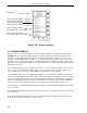
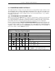
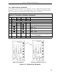
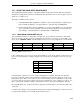

Table 3-3. Procedure to Alter a Datapoint
Step Press
Once
Shift
Result
Press to
Locate
Target
Char.
Result
1
●
Puts instrument in engineering mode.
2If
CONFIGURE
does not appear, press
2
.
3
3
Displays entry line:
POINT .
4CPuts
C
on entry line:
POINT .C
.
5.C
∆
1Shifts
C
and puts
1
on entry line:
POINT .C1
.
6.C1
∆
7Shifts
C1
and puts
7
on entry line:
POINT .C17.
7.C17
∆
5Shifts
C17
and puts
5
on entry line:
POINT .C175.
8
3
Enters address to display datapoint contents. The address with the contents
are displayed as follows:
C175 80.0000
.
9
hold
.
locator
C175
contents shifted right; only the locator
point remains on the entry line:
C175 .
10 9 Puts
9
on entry line:
C175 .9
.
11 .9
∆
0Shifts
9
and puts
0
on entry line:
C175 .90
.
12
3
Enters the value
90
in datapoint
C175
.
13
●
Returns instrument to operator mode.
Note:
∆
= space.
Figure 3-10. Entry
Line Ten Character
Field
3.4.3 ALTERING A DATAPOINT
The procedure in Table 3-3 illustrates how to alter the contents of data-
point C175, which is ANI2 Alarm Limit 1, from 80 to 90. Figure 3-10 is
provided to show the maximum input character length for the engineer-
ing mode edit line. The edit line can accept ten characters. The full ten
character field is used primarily for the
A type datapoint
text strings
(tag names). Reference Table 4-1 in Section 4 for information about the
datapoint types. Note that in Figure 3-10, the
PO
is residual from the
prompt
POINT
and that the character field string starts with 1 and ends
with 0 (underlined in the figure) to illustrate 10 characters.
53IT5100 Indicator/Totalizer
3-10