
Manual
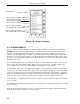

3.4 ENGINEERING MODE OVERLAYS
The engineering mode overlays are used to make the necessary parameter entry selections for the
operator displays and to configure the Datalink communications port. The entries are made to ad-
dressed datapoints via the overlay single edit line at the bottom of the display. It should be noted
that engineering mode has a 20 second timeout if it is accessed and its functions (e.g., configure
or display) are not used.
3.4.1 RESPONDING TO THE PROMPT KEY?
When the password prompt
KEY?
appears, it indicates a password was set with an external device
(e.g. Hand Held Configurer, PC, etc.). The password can not be set via the front panel push but-
tons. A password key is a maximum of 10 numeric characters (numbers 0-9 only). It does not im-
pede display functions in engineering mode but must be unlocked to perform configuration
functions. A password key is
NOT SET FOR NEW INSTRUMENTS
from the factory; therefore, if it
is set, it must have been done locally. The password must first be obtained from the originator be-
fore the procedure in Table 3-1 can be used to access the engineering mode configuration function
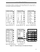
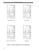
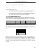
capabilities. Figure 3-8 illustrates the
CONFIGURE
prompt, the
KEY?
prompt, the key
222222
en-
tered on the edit line, and the
POINT
input query.
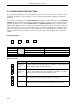
Table 3-1. Entering a Key Password
Step Press
Once
Shift
Result
Press to
Locate
Target
Char.
Result
1
●
Puts instrument in engineering mode.
2If
DISPLAY
appears instead of
CONFIGURE
, press
2.
3
3
Displays password query:
KEY? .
4 2 Puts first password number on entry line:
KEY? .2
.
5.2
∆
2Shifts
2
and puts second password number on
entry line:
KEY? .22
.
6.22
∆
2Shifts
22
and puts third password number on
entry line:
KEY? .222.
7 Repeat step 6 until all of the password characters are entered.
8
3
It enters the password key and displays the entry
line:
POINT .
The engineering mode
configuration function is now accessible for use.
Note:
∆
= space.
Section 3. Displays and Push Buttons
3-7