
Manual


Indicator/Totalizer
53IT5100 Indicator/Totalizer
Section 1
Introduction
Section 2
Installation
Section 3
Displays and
Push Buttons
Section 4
Configuration
Parameters
Appendix C
Database
Appendix B
Communica-
tions
Appendix A
Discrete
Contact
Output
Section 5
Maintenance
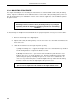
1-8
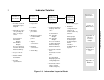
Figure 1-3. Information Layout of Book
Reference
Information:
•
Product overview
with input/output
diagram.
•
Illustrations of the
six operating dis-
plays on single
sheet:
Four Channel
Ch1&2 Bar
Graphs
Ch 3&4 Bar
Graphs
Process Readout
Totalizer Readout
Alarm Summary
•
Scope of book.
•
Model number
breakdown.
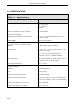
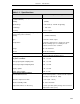
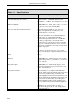
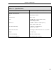
•
Product
specifications.
•
Data format types.
•
Database
configuration pa-
rameters in
module tables by
function:
Analog Input
Analog Output
Contact Input
Contact Output
Alarm
Totalizer
Communication
System
•
Introduction.
•
Indicator/Totalizer
displays with call-
outs:
Four Channel
Ch. 1&2 Bar
Graphs
Ch. 3&4 Bar
Graphs
Process Readout
Totalizer Readout
Alarm Summary
Alarm Indications
•
Push button defini-
tions.
Push button exam-
ples:
Key Password
Displaying and al-
tering datapoints.
•
Push button alter-
natives (Hand
Held Configurer).
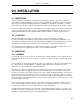
•
Inspection.
•
Location.
•
Mounting
procedure.
•
Wiring procedures
for AC and DC
power.
•
Signal
connections.
•
Datalink
connections.
•
Grounding.