INSTRUCTION MANUAL Micro-DCI™ Indicator/Totalizer 53IT5100A PN24479 Rev.
MicroMod Automation, Inc. The Company MicroMod Automation is dedicated to improving customer efficiency by providing the most ost-effective, application-specific process solutions available. We are a highly responsive, application-focused company with years of expertise in control systems design and implementation. We are committed to teamwork, high quality manufacturing, advanced technology and unrivaled service and support.
Contents Table of Contents 1.0 INTRODUCTION 1.1 1.2 1.3 1.4 PRODUCT OVERVIEW . . . . SCOPE OF BOOK . . . . . . . MODEL NUMBER BREAKDOWN SPECIFICATIONS . . . . . . . 1-1 . . . . . . . . . . . . . . . . . . . . . . . . . . . . . . . . . . . . . . . . . . . . . . . . . . . . . . . . . . . . . . . . . . . . . . . . . . . . . . . . . . . . . . . . . . 1-1 . . 1-7 . . 1-9 . 1-10 2.0 INSTALLATION 2.1 INSPECTION . . . . . . . . . . . . . . . . . . . . . . . . 2.2 LOCATION . . . . . . . . .
53IT5100 Indicator/Totalizer 5.0 MAINTENANCE 5.1 5.2 5.3 5.4 5.5 5.6 5.7 5-1 SERVICE APPROACH . . . . . . . . . . . . . . PARTS REPLACEMENT . . . . . . . . . . . . . CALIBRATION . . . . . . . . . . . . . . . . . ERROR AND HARDWARE MALFUNCTION MESSAGES RESETTING THE INSTRUMENT . . . . . . . . . . PARTS LIST . . . . . . . . . . . . . . . . . . SUPPLEMENTAL INFORMATION . . . . . . . . . . . . . . . . . . . . . . . . . . . . . . . . . . . . . . . . . . . . . . . . . . . . . . . . . . . . . . . . . . .
3IT5100 Indicator/Totalizer List of Figures Figure Figure Figure Figure Figure Figure Figure Figure Figure Figure Figure Figure Figure Figure Figure Figure Figure Figure Figure Figure Figure Figure Figure Figure Figure Figure Figure Figure Figure Figure Figure iii 1-1. Indicator/Totalizer Operator Displays . . . . . . . 1-2. Indicator/Totalizer Illustrated Overview . . . . . . 1-3. Information Layout of Book . . . . . . . . . . . 2-1. Outline Dimensions and Panel Cut-Out Requirements 2-2.
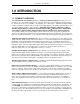
Section 1. Introduction 1.0 INTRODUCTION 1.1 PRODUCT OVERVIEW The 53IT5100 Indicator/Totalizer provides a suite of six operator displays to monitor process activity for up to four independent process variables and also provides integration and totalization for each of the four process variables. The displays are of three types: dynamic bar graph, digital readout, and alarm summary. There are three bar graph displays, two digital readout displays, and one alarm summary display.
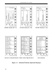
53IT5100 Indicator/Totalizer Quad Bar Graph (Chs. 1-4) Dual Bar Graph (Chs. 1&2) Quad Process Digital Readout Quad Totalizer Digital Readout Dual Bar Graph (Chs. 3&4) Alarm Summary Figure 1-1.
Section 1. Introduction partition, and partitions three and four are occupied by the two contact inputs. All six tag names for this display are selectable entries. There are also selectable entries that define how each contact input display message is differentiated from the others to indicate an alarm state.
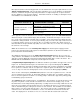
53IT5100 Indicator/Totalizer SIDE BACK ANO0 ANI0 LUG 1 12 SIGNAL ANI1 ANI2 TOTALIZERS (4) CONNECTOR ANI3 TB1 LUG 12 DATABASE CCI0 CCO0 10 SIGNAL CCI1 CCO1 CONNECTOR DATALINK POWER CONNECTOR INPUT/OUTPUT DIAGRAM SCALLOPED SIDES OF CONNECTOR LUG 13 LUG 22 TB2 LUG 5 LUG 1 AND 22 PIN SOCKET TO REMOVE SIGNAL CONNECTOR, GRASP SIDES FIRMLY WITH THUMB AND FOREFINGER, ROCK GENTLY FROM TOP TO BOTTOM (NOT SIDE TO SIDE) AND PULL STRAIGHT OUT.
Section 1. Introduction Directly beneath the horizontal keypad and concealed behind the front panel pull-down door is the RS-232 Configuration Port. This port provides instrument access to the database for alternative methods, other than using the front panel push buttons in engineering mode, to input selections into the database for the operator displays.
53IT5100 Indicator/Totalizer rollover value. The dropout value specifies a minimum input value required to increment the running total. All of the selectable entries for the Indicator/Totalizer are parameter entries to the database. The database is subdivided into modules composed of datapoints that are accessed by the instruction code as the instrument performs its functions.
Section 1. Introduction 1.2 SCOPE OF BOOK Information in this book is presented as text, visuals, and tables. All three are required, but the text has been minimized wherever possible. The tables provide either summary information or procedural steps to perform a specific task.
1-8 Indicator/Totalizer Section 3 Displays and Push Buttons • Product overview with input/output diagram. • Inspection. • Introduction. • Data format types. • Location. • Illustrations of the six operating displays on single sheet: • Mounting procedure. • Indicator/Totalizer displays with callouts: • Database configuration parameters in module tables by function: Four Channel Ch1&2 Bar Graphs Ch 3&4 Bar Graphs Process Readout Totalizer Readout Alarm Summary • Scope of book.
Section 1. Introduction 1.3 MODEL NUMBER BREAKDOWN TYPE NO. 53IT SERIES NO. 53IT5100 INDICATOR TOTALIZER 53IT51 A 2 1 A Engineering File Reference: Power Requirements AC (120/240) DC (24) Functional Requirements Standard Standard with Factory Configuration Design Level 1 2 1 2 A Enclosure Type DIN 72 x 144 mm Bezel Main Rear Terminal Requirement Standard Rear Terminal Chassis Standard Safety Classification General Purpose FM Approved: Nonincendive for Class I, Div.
53IT5100 Indicator/Totalizer 1.4 SPECIFICATIONS Table 1-1. Specifications Item Specification(s) Power Requirements (as specified) 22 - 26 V dc 108 - 132 V rms 216 - 264 V rms 50/60 Hz Power Consumption (ac/dc operation) 36 VA maximum Internal Power Supply: Available Power Output for Transmitters 25 V dc ± 1 V dc @ 80 mA maximum, short circuit protected.
Section 1. Introduction Table 1-1. Specifications Item Specification(s) Analog Output (ANO0) Signal (is referenced to power common) Quantity 1 (ANO0) Signal Range 0 - 20 mA dc (4 - 20 mA dc typically) Load Range 0 - 750 ohms Accuracy Switch Output (CCO0, CCO1) Signals (are referenced to power common) Quantity ± 0.
53IT5100 Indicator/Totalizer Table 1-1. Specifications Item Environmental Characteristics (Cont): Transient Immunity (all circuits) Specification(s) ANSI C37.90a - 1974/IEEE Std 472- 974: Ring Wave: 1.5 MHz, 3 kV, 60 pulses/s for 2.0 s EMI Susceptibility SAMA PMC 33.1-1978: Class 3-abc: no effect at 30 V/m, at 27, 146, and 446 MHz Enclosure Classification/Environment Panel Mounted Equipment: No enclosure rating. Designed to be installed in a user provided panel or enclosure.
Section 1. Introduction Table 1-1. Specifications Item Specification(s) Physical Characteristics Material of Construction: Case Steel, black enamel Circuit Boards Glass epoxy Bezel ULTEM 1000 (Polyethermide Resin) Flammability-UL94 5V Dimensions 2.844W x 5.656H x 12.906L (inches) 73W x 144H x 329L (mm) Flush Panel Mounting 0.125 inch - 1 inch thickness (3.2 mm - 25.4 mm) Electrical Connections Screw type terminal block at rear of casework Weight 5 lbs (2.
Section 2. Installation 2.0 INSTALLATION 2.1 INSPECTION A list of all items in the shipment is attached to the shipping container. Inspect the equipment upon arrival for damage that may have occurred during shipment. All damage claims should be reported to the responsible shipping agent before installation is attempted. If damage is such that faulty operation is likely to result, the MicroMod Customer Service Department should be notified.
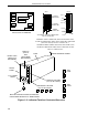
53IT5100 Indicator/Totalizer 2.3.2 MOUNTING PROCEDURE For single and multiple case mounting the instruments are furnished with a trim collar (mounting frame). Figure 2-2 illustrates the installation and use of the trim collar (mounting frame). Trim collars (mounting frames) are available in various sizes and are supplied to conform with the particular panel cut-out. NOTE Mounting brackets and trim collars (mounting frames) are packaged separately.
Section 2. Installation Figure 2-1.
53IT5100 Indicator/Totalizer Figure 2-2. Single or Multiple Panel Mounting Figure 2-3.
Section 2. Installation 2.4 CONNECTIONS 2.4.1 PREPARATORY The 53IT5100 can be configured for one to four analog inputs (ANI0-3), one analog output (ANO0), two control contact inputs (CCI0 and 1), two control contact outputs (CCO0 and 1) and Datalink network interconnectivity. Therefore, prior to making electrical connections, the particular instrument configuration should be determined with all assigned inputs and outputs identified to assure proper signal routing. 2.4.
53IT5100 Indicator/Totalizer 2.4.2.1 POWER INPUT (AS SPECIFIED) 2.4.2.1.1 DC Power Reference Figure 2-4 and connect the remote 24 V dc power supply to the instrument as follows: 1. Connect (+) input line, via remote SPST switch, to terminal L1. 2. Connect (-) input line to the system bus bar. The bus bar should be connected to a good earth ground (#8 AWG wire is recommended). Individual wires should be run from the controller Power Common (PC ) and Signal Common (SC ) terminals to the bus bar.
Section 2. Installation 2.4.2.3 CONTACT INPUT TO CCI0 AND CCI1 Separate contact input signals to CCI0 and CCI1 can be used for alarm inputs. One side of each remote contact must be connected to power common as illustrated in Figure 2-4. Minimum opened or closed recognition time for a remote contact must be 0.05 seconds. 2.4.2.4 CURRENT OUTPUT FROM ANO0 A current output signal is available for re-transmission of one of the input signals ANI0 through ANI3.
2-8 53IT5100 Indicator/Totalizer Figure 2-4.
Section 2. Installation 2-9 Figure 2-5.
Section 3. Displays and Push Buttons 3.0 DISPLAYS AND PUSH BUTTONS This section provides illustrations with item call-outs of the six operator displays, alarm overlays, and engineering mode overlays. Where applicable, datapoints are identified parenthetically with the display item call-outs. The datapoints are defined in Section 4.
53IT5100 Indicator/Totalizer ANI0 Tag Name (A224) ANI1 Tag Name (A225) ANI0 Span (C256) ANI1 Span (C257) 50 Segment Graph Scale 50 Segment Graph Scale ANI0 Alarm Limit 1 (C103) ANI1 Alarm Limit 1 (C139) ANI0 Alarm Limit 2 (C104) ANI1 Alarm Limit 2 (C140) ANI0 Process Variable ANI1 Process Variable ANI0 Zero (C276) ANI1 Zero (C277) ANI0 Digital Readout (H000)* ANI0 Units (A298) ANI1 Digital Readout (H001)* ANI1 Units (A299) *Display only. Figure 3-2.
Section 3. Displays and Push Buttons ANI0 Tag Name (A224) ANI0 Digital Readout (H000)* ANI0 Units (A298) ANI1 Tag Name (A225) ANI1 Digital Readout (H001)* ANI1 Units (A299) ANI2 Tag Name (A226) ANI2 Digital Readout (H002)* ANI2 Units (A300) ANI3 Tag Name (A227) ANI3 Digital Readout (H003)* ANI3 Units (A301) *H000 - H003 are display only. Figure 3-4.
53IT5100 Indicator/Totalizer Display Title ANI0 ANI1 ANI2 ANI3 Tag Tag Tag Tag Name Name Name Name (A224) (A225) (A226) (A227) CCI0 Tag Name (A262) CCI0 Display Message (A055) CCI1 Tag Name (A263) CCI1 Display Message (A056) Figure 3-6. Alarm Summary 3.2 ALARM OVERLAY Any one of the six operator displays can have the upper quadrant of the display overlaid with an ALARM indicator. An alarm indication warns of variation changes that exceed tolerance limits; the process may require immediate attention.
Section 3. Displays and Push Buttons The alarm banner blinking is stopped by pressing the Mode ( ● ) push button on the front panel; the alarm banner remains on the display, but does not blink, until the process variable returns to a value within the alarm limit (passed dead band). Quad Bar Graph (Chs. 1-4) Dual Bar Graph (Chs. 1&2) Quad Process Digital Readout CCI-0 ALARM A Displays for Settings of Display Mode (SMA), Alarm Enable (SAA), and Contact Input (CCI0). (See Table 4-5 of Section 4.
53IT5100 Indicator/Totalizer 3.3 FRONT PANEL PUSH BUTTONS The front panel push buttons are repeated here from Section 1 because they are used in the engineering mode display overlay examples to enter a key password, display a datapoint, and alter a datapoint. To the right of the display is the vertical keypad and directly beneath the display is the horizontal keypad.
Section 3. Displays and Push Buttons 3.4 ENGINEERING MODE OVERLAYS The engineering mode overlays are used to make the necessary parameter entry selections for the operator displays and to configure the Datalink communications port. The entries are made to addressed datapoints via the overlay single edit line at the bottom of the display. It should be noted that engineering mode has a 20 second timeout if it is accessed and its functions (e.g., configure or display) are not used. 3.4.
53IT5100 Indicator/Totalizer CONFIGURE Prompt KEY? Prompt A Key Entered on the Edit Line POINT Query Figure 3-8.
Section 3. Displays and Push Buttons 3.4.2 DISPLAYING A DATAPOINT The following procedure illustrates how to display the contents of datapoint C175, which is ANI2 Alarm Limit 1. Figure 3-9 contains supporting illustrations for the display procedure described in Table 3-2. (Notice in these illustrations that ANI-2 Alarm Limit 1 is set at 80.) Table 3-2. Procedure to Display a Datapoint Step 1 2 3 4 Press Once ● Shift Result Press to Locate Target Char. Puts instrument in engineering mode.
53IT5100 Indicator/Totalizer 3.4.3 ALTERING A DATAPOINT The procedure in Table 3-3 illustrates how to alter the contents of datapoint C175, which is ANI2 Alarm Limit 1, from 80 to 90. Figure 3-10 is provided to show the maximum input character length for the engineering mode edit line. The edit line can accept ten characters. The full ten character field is used primarily for the A type datapoint text strings (tag names). Reference Table 4-1 in Section 4 for information about the datapoint types.
Section 3. Displays and Push Buttons 3.5 FRONT PANEL PUSH BUTTON ALTERNATIVES There are four alternative methods other than the front panel push buttons for accessing and changing database parameters. All four methods to display and/or alter database parameters are listed as follows: 1. Using an IBM PC compatible running the MC5FIG.EXE configuration program that is supplied as part of the 53HC3300 software package. This procedure is included in the Instruction Bulletin (IB 53HC3300) with the software. 2.
3-12 53IT5100 Indicator/Totalizer Figure 3-11.
Section 3. Displays and Push Buttons 3.5.1 USING THE HAND HELD CONFIGURER The Hand Held Configurer (HHC) is a portable terminal designed to interface with the instrument through the configuration port that is located behind the pull-down door on the front panel of the instrument (see Figure 1-2). The HHC is available in two versions: 1. A Standard HHC with capabilities to display or alter specifically addressed parameters in the instrument database. The part number to order this HHC is 698B182U01. 2.
53IT5100 Indicator/Totalizer 3.5.1.2 DISPLAYING A DATABASE PARAMETER To DISPLAY a database parameter, press D and enter the parameter ID, then press ENTER. The current value of the parameter is displayed. The parameter ID is the data type identifier (B, L, C, H, F, and A) and point number as described in Table 4-1 of Section 4. For example, to display the value of datapoint B12, press: D B12 . The value presently assigned to B12 is displayed.
Section 3. Displays and Push Buttons 3.5.1.4 SETTING OR CHANGING A PASSWORD KEY As a security feature, the instrument can be configured so that a password key is required to access the Engineering Mode configuration function. The password key can only be set by the Hand Held Configurer, or the 53HC3300 or 53WS5000 software packages via a PC, or the SUPERVISOR-PC, and not by the instrument front panel push buttons.
53IT5100 Indicator/Totalizer 2. If F2 is selected, the following menu appears: F2-DATABASE F3-PROGRAM (not applicable) Based on which selection from this menu is made the following operations can occur: • F2- DATABASE: This operation copies the entire database, all B, L, C, H, and A, datapoint values, in the instrument to the storage cartridge. Transfer takes approximately 12 seconds. • F3- PROGRAM: This operation is not applicable for this instrument.
Section 4. Configuration Parameters 4.0 CONFIGURATION PARAMETERS The configuration parameters provide the latitude to define the instrument’s personality attributes, so that while still functioning within its designed specifications, it can perform application requirements with greater refinement. Typical configuration parameters are the instrument’s indicator zero point and span, the display tag names, engineering units of the displayed process value, and alarm limits, etc.
53IT5100 Indicator/Totalizer 4.3 CONFIGURING THE DATABASE MODULES The datapoints in the database modules must be changed to reflect required alterations in the factory standard configuration or when the instrument is re-configured. There are generally four datapoint parameter types contained in the eight database modules. The parameter types affect Datalink communications, display indications, input-output signals, and alarm conditions. The eight database modules are described in Table 4-2.
Section 4. Configuration Parameters Table 4-3. Analog Input (ANI) Module Purpose: This module is used to configure input voltage characteristics (e.g., input voltage range), and how the input signals are interpreted (linear or square root representation). Title Symbol ANI Datapoint Default ANI0 ANI1 ANI2 ANI3 ANI0 ANI1 ANI2 ANI3 H000 H001 H002 H003 0 0 0 0 This is the value in engineering units of the measured input after all signal conditioning has been applied.
53IT5100 Indicator/Totalizer Table 4-3. Analog Input (ANI) Module Purpose: This module is used to configure input voltage characteristics (e.g., input voltage range), and how the input signals are interpreted (linear or square root representation).
Section 4. Configuration Parameters Table 4-4. Analog Output (ANO) Module Purpose: The primary purpose of this module is to set the 0 - 20 mA output signal relative to the displayed percent and to select the analog input signal (ANI0-3) that is to be routed to the analog output (ANO0). Title Symbol ANO0 Datapoint Default Attribute Analog Output (Display Only) ANO0 C000 0 The value in this datapoint represents the percent of output to be generated by hardware (e.g., 100% output = 20 mA).
53IT5100 Indicator/Totalizer Table 4-5. Contact Input Module (CCI) Purpose: This module allows the action of the CCIs to be reversed (normally a closed contact = 1, but can be changed to = 0). Title Symbol CCI Datapoint Default Attribute Contact Input (Display Only) CCI0 CCI1 CCI0 L000 CCI1 L001 0 0 When open, a 4 - 24 V dc input signal = 0 when IINV = 0. When open, a 4 - 24 V dc input signal = 1 when IINV = 1. When closed, a < 1 V dc input signal = 1 when IINV = 0.
Section 4. Configuration Parameters Table 4-6. Contact Output Module (CCO) Purpose: This module allows the action of the CCOs to be reversed (normally a closed contact = 1, but can be changed to = 0) and is used to select the signal or condition that activates the CCO.
53IT5100 Indicator/Totalizer Table 4-7. Alarm Module Purpose: The primary purpose of this module is to set the instrument’s Alarm Index mode, Alarm Limits 1 & 2, and Alarm Dead Band. Title Alarm Index Symbol CON Datapoint Default Attribute AIX0 AIX1 AIX2 AIX3 ALRM0 ALRM1 ALRM2 ALRM3 B335 B340 B345 B350 1 1 1 1 This parameter defines the Alarm Active (PA1 & PA2) interpretation of the two Alarm Limits (PL1 & PL2).
Section 4. Configuration Parameters Table 4-7. Alarm Module Purpose: The primary purpose of this module is to set the instrument’s Alarm Index mode, Alarm Limits 1 & 2, and Alarm Dead Band.
IT5100 Indicator/Totalizer Table 4-8. Totalizer Module Purpose: The totalizers provide a running total of each analog input (ANI0-3). This module is used to set input scaling factors, rollover and dropout values, and to define display tags for each totalizer.
Section 4. Configuration Parameters Table 4-8. Totalizer Module Purpose: The totalizers provide a running total of each analog input (ANI0-3). This module is used to set input scaling factors, rollover and dropout values, and to define display tags for each totalizer. Title Actual Total (Display Only) Output Pulse Symbol TM Datapoint Default Attribute TO0 TO1 TO2 TO3 TM0 TM1 TM2 TM3 H032 H033 H034 H035 0 0 0 0 This parameter indicates the integer value of the total accumulation.
53IT5100 Indicator/Totalizer Table 4-9. Communication Module Purpose: This module is used to configure the Datalink port parameters (e.g., baud rate, parity selection, etc.). Title Symbol Data- Depoint fault Instrument Address IA B001 Baud Rate BR B002 0 Attribute It identifies the address of this instrument on the Datalink network. Each unit connected to the Datalink network must have its own unique address. Valid addresses are from 0 - 31.
Section 4. Configuration Parameters Table 4-10. System Module Purpose: This module is used to set the instrument tag name and the display brightness. Title Symbol System Module Datapoint Default Display Brightness Index BRIGHT B012 4 Model Number Low (Display Only) A190 Factory Set It contains the first ten characters of the model number. Model Number High (Display Only) A191 Factory Set It contains the last ten characters of the model number.
Section 5. Maintenance 5.0 MAINTENANCE NOTE The factory set calibration constants for ANI0-3 and ANO0 are applicable only for the main printed circuit board supplied in the particular instrument. This data is recorded on a calibration sheet supplied with the instrument. The data should be retained to facilitate easy field recalibration in the event one or more of the constants is inadvertently changed. 5.
53IT5100 Indicator/Totalizer After the front display panel is removed, the main printed circuit board can be accessed. The main printed circuit board also has the power supply as well as the microprocessor circuitry. To remove the main PCB, use its front edge board ejector to pull it free from the rear terminal board slot and carefully slide it from the case. Disconnect the front display panel flat ribbon cable from the main PCB.
Section 5. Maintenance 5.4 ERROR AND HARDWARE MALFUNCTION MESSAGES • Entire Display Flashes - The watchdog timer has timed out. • CPU RAM FAILURE - IC U1 is bad. • ROM CHKS FAILURE - IC U3 is bad. 5.5 RESETTING THE INSTRUMENT The instrument can be reset either by cycling the power, or by carefully pressing the reset button by inserting a thin wire, such as a paper clip, through the small hole in the upper left corner of the front bezel. (See Figure 1-2 for the location of the reset hole.
53IT5100 Indicator/Totalizer 5.6 PARTS LIST The parts list is provided in Table 5-1 and the parts breakdown is illustrated in Figure 5-1. Table 5-1.
Section 5. Maintenance 5-5 Figure 5-1.
53IT5100 Indicator/Totalizer Figure 5-2.
Section 5. Maintenance Figure 5-3.
Appendix A. Discrete Contact Output CCO APPENDIX A: DISCRETE CONTACT OUTPUT CCOs The discrete output CCOs are not mechanical contact closures but NPN Transistors that are analogous to single pole, single throw switches with one terminal connected to power common. This circuit type layout is commonly called an Open Collector Output. (See Figure A-1.) Capability limits of each CCO are as follows: • 50 mA maximum current flow when closed. • 30 V dc maximum tolerance voltage when open.
53IT5100 Indicator/Totalizer Figure A-1. CCO Circuit and its Equivalent Figure A-2.
Appendix A. Discrete Contact Output CCO Figure A-3. Operating CCOs in Parallel Figure A-4. CCO with Solid State Relay Figure A-5.
Appendix B. Communications APPENDIX B: COMMUNICATIONS B.1 STANDARD COMMUNICATIONS Two digital communication channels are provided with this instrument: 1) There is a configuration port that is an RS-232 serial interface. It is accessed via a 5 pin mini-DIN connector located under the pull-down door on the front panel (see Figure 1-2). It is used to configure instrument parameters for selected operational characteristics.
53IT5100 Indicator/Totalizer B.1.1 CONFIGURATION To initialize the instrument for binary communications, configure the instrument as described in Table B-1, Column 3 (Set Up ). Table B-1. Communication Module Purpose: This module is used to configure the Datalink port parameters (e.g., baud rate, parity selection, etc.). Title Datapoint Set Up Default Instrument Address B01 S 0 Baud Rate B02 S Attribute It identifies the address of this instrument on the Datalink network.
Appendix B. Communications B.1.2 PROTOCOL The Datalink protocol requires the host or SUPERVISOR-PC to initiate all transactions. There are two basic categories for all of the Datalink message types: Interrogate - used to read data from an addressed instrument, and Change used to alter a value in an addressed instrument. The addressed instrument decodes the message and provides an appropriate response. The protocol definitions for the Datalink message types are provided in Table B-2. Table B-2.
53IT5100 Indicator/Totalizer B.1.3 MESSAGE TYPES The types of messages that are sent between the host or SUPERVISOR-PC and the Datalink network instrument are formatted as follows: HOST OR SUPERVISOR-PC TO INSTRUMENT: 1. INTERROGATE - This message requests up to 20H consecutively stored bytes, beginning at the specified memory address location of the addressed instrument. 01111110 E0H + I.A. NUM LO ADD HI ADD LRC 2. CHANGE - This message sends up to 20H bytes of new data to the addressed instrument.
Appendix B. Communications B.1.4 COMMUNICATION TRANSACTION EXAMPLES Transaction A Example - Host or SUPERVISOR-PC requests 9 bytes of data beginning at hexadecimal memory address 1000H from the instrument at Datalink address 03. 1. Host or SUPERVISOR-PC sends INTERROGATE message. 01111110 11100011 00001001 00000000 00010000 11111100 SOH Command + I.A. NUM LO ADD HI ADD LRC 2. Instrument sends RESPONSE message. 01111110 00100011 00001001 00000000 00010000 XXXXX XXXXX XXXXX SOH Command + I.A.
53IT5100 Indicator/Totalizer B.1.5 CALCULATING DATA ADDRESSES If communications software must be generated to accommodate unique Datalink applications requirements, then the instrument memory address scheme must be known for proper data bit (e.g., L data type) and data byte (e.g., B, C, H, and A data types) memory location determination. Note: Numbers used in this section that are expressed in hexadecimal notation (base 16) are identified with an H after the number.
Appendix B. Communications Table B-3. Instrument Memory Address Scheme Data Type H Base Memory Address F00H A (F)* 1400H Byte Size 5 Data Format Represents high precision floating point values that have a resolution of one part in 2 billion (31 bits) and a dynamic range of ± 10 38 . The first four bytes represent a 2’s complement notation in fractional form (2-n) whose absolute value is between 0.5 and 0.9999. The fifth byte is the power of 2 in 2’s complement notation.
53IT5100 Indicator/Totalizer B.1.6 SOFTWARE CHARACTERISTICS 1. Transparency Rule - whenever 7E hexadecimal is transmitted as anything other than SOH, a 00 byte will be inserted directly following it (byte stuffing). 2. All transactions are initiated by the Host or SUPERVISOR-PC. 3. All instruments begin their response within 10 ms after the end of the transmission by the Host or SUPERVISOR-PC; otherwise, a faulty transmission may be assumed. 4. Illegal messages received by the instruments are ignored. 5.
Appendix C. Database APPENDIX C: DATABASE The database contains five datapoint types. Each datapoint type represents a specific data format: whole integers, alphanumeric text strings, etc. The datapoint types are defined in Table C-1 and the database is listed in alphanumeric order in Table C-2. The gray-tone shading in the Symbol cell of a datapoint indicates the datapoint does not have an assigned symbol. Table C-1.
53IT5100 Indicator/Totalizer Table C-2.
Appendix C. Database Table C-2.
53IT5100 Indicator/Totalizer Table C-2.
Appendix C. Database Table C-2.
The Company’s policy is one of continuous product improvement and the right is reserved to modify the information contained herein without notice, or to make engineering refinements that may not be reflected in this bulletin. Micromod Automation assumes no responsibility for errors that may appear in this manual. © 2004 MicroMod Automation, Inc. Printed in USA MicroMod Automation, Inc. 75 Town Centre Drive Rochester, NY USA 14623 Tel. 585-321-9200 Fax 585-321-9291 www.micromodautomation.