
Operating instructions

6 Commissioning Issue 10/06
MICROMASTER 440
64 Operating Instructions (Compact)
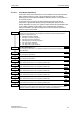
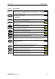
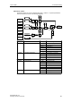
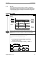
Controller structures
These structures are selected using parameters P2200 and P2251.
P2200 = 0:0
2)
P2251 = 0
1
P2200 = 1:0
2)
P2251 = 0
2
P2200 = 0:0
1)
P2251 = 1
3
P2200 = 1:0
1)
P2251 = 1
4
−
−
−
ON: active
OFF1/3: active
ON: -
OFF1/3: -
ON: -
OFF1/3: -
SUM PID controller
RFG PID-RFG
1) will take change with drive running
2) change only taken when drive stopped
VSD *
Dancer control
ON: active
OFF1/3: active
ON: active
OFF1/3: active
ON: active
OFF1/3: active
ON: active
OFF1/3: -
ON: -
OFF1/3: active
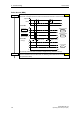
Setpoint via
PID control
VSD *
* Variable speed drive (VSD)
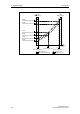
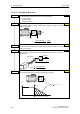
PID control
PID
MOP
ADC
PID
SUM
PID
PID
FF
USS
BOP link
USS
COM link
CB
COM link
ADC2
P2254
P2253
PID
RFG
PID
PT1
−
∆
PID
P2200
P2264
PID
PT1
PID
SCL
&
P2251
Output
PID
0
1
Motor
control
P2257
P2258
P2261
P2271
P2269
P2270
P2265
P2280
P2285
0
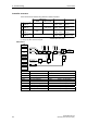
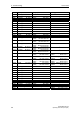
Parameter Parameter text Example
P2200 BI: Enable PID controller P2200 = 1.0 PID controller active
P2253 CI: PID setpoint P2253 = 2224 PID-FF1
P2264 CI: PID feedback P2264 = 755 ADC
P2267 Max. PID feedback P2267 Adapt to the application
P2268 Min. PID feedback P2268 Adapt to the application
P2280 PID proportional gain P2280 Determined by optimizing
P2285 PID integral time P2285 Determined by optimizing
P2291 PID output upper limit P2291 Adapt to the application
P2292 PID output lower limit P2292 Adapt to the application