
Operating instructions

Issue 10/06 Contents
MICROMASTER 440
Operating Instructions (Compact)
3
Contents
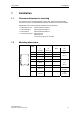
1 Installation............................................................................................................... 5
1.1 Clearance distances for mounting ............................................................................ 5
1.2 Mounting dimensions................................................................................................ 5
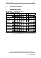
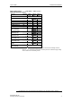
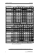
2 Electrical Installation.............................................................................................. 6
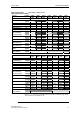
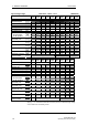
2.1 Technical Specifications ........................................................................................... 6
2.2 Power Terminals..................................................................................................... 13
2.3 Control terminals..................................................................................................... 21
2.4 Block diagram ......................................................................................................... 22
3 Factory setting ...................................................................................................... 23
3.1 50/60 Hz DIP switch................................................................................................ 23
4 Communications................................................................................................... 24
4.1 Establishing communications MICROMASTER 440 ⇔ STARTER........................ 24
4.2 Establishing communications MICROMASTER 440 ⇔ AOP................................. 24
4.3 Bus interface (CB)................................................................................................... 25
5 BOP / AOP (Option) .............................................................................................. 26
5.1 Buttons and their Functions .................................................................................... 26
5.2 Changing parameters using as an example P0004 "Parameter filter function"...... 27
6 Commissioning..................................................................................................... 28
6.1 Quick commissioning.............................................................................................. 28
6.2 Motor data identification.......................................................................................... 32
6.3 Magnetizing current ................................................................................................ 32
6.4 Commissioning the application............................................................................... 34
6.4.1 Serial Interface (USS)............................................................................................. 34
6.4.2 Selection of command source ................................................................................ 34
6.4.3 Digital input (DIN).................................................................................................... 35
6.4.4 Digital outputs (DOUT) ........................................................................................... 36
6.4.5 Selection of frequency setpoint............................................................................... 37
6.4.6 Analog input (ADC)................................................................................................. 38
6.4.7 Analog output (DAC)............................................................................................... 39
6.4.8 Motor potentiometer (MOP) .................................................................................... 40
6.4.9 Fixed frequency (FF)............................................................................................... 41
6.4.10 JOG......................................................................................................................... 42
6.4.11 Ramp function generator (RFG) ............................................................................. 43
6.4.12 Reference/limit frequencies .................................................................................... 44
6.4.13 Inverter protection................................................................................................... 45
6.4.14 Motor protection...................................................................................................... 45
6.4.15 Encoder................................................................................................................... 47
6.4.16 V/f control................................................................................................................ 48