
Operating instructions


TM 11574A-OI
2-61
NOTE
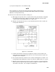
The controlling probe in the perishable range will be the SUPPLY air probe and the
controlling probe in the frozen range will be the RETURN air probe.
(3) Controller.
CAUTION
Do not remove wire harnesses from controller unless you are grounded to the unit frame
with a static safe wrist strap.
CAUTION
Unplug all controller wire harness connectors before performing arc welding on any part
of the container.
NOTE
Do not attempt to service the controller. Breaking the seal will void the warranty.
NOTE
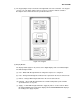
Do not attempt to use an ML2i PC card in an ML3 equipped unit. The PC cards are
physically different and will result in damage to the controller. The Micro-Link 3 controller
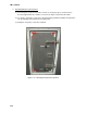
is a single module microprocessor as shown in Figure 2-27. It is fitted with test points,
harness connectors and a software card programming port.
Figure 2-26. Micro-Link 3 Controller.
LEGEND
1. Mounting Screw
2. Micro-Link 3 Controller
3. Connectors
4. Test Points
5. Fuses
6. Control Circuit Power Connection (Located in
back of controller)
7. Software Programming Port
8. Battery Pack