
Operating instructions


TM 11574A-OI
2-59
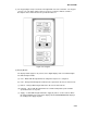
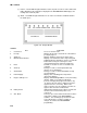
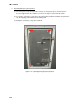
(1) The keypad (Figure 2-25) is mounted on the right-hand side of the control box. The keypad
consists of 11 push button switches that act as the user’s interface with the controller.
Descriptions of the switch functions are provided in Table 2-1.
Figure 2-24. Keypad.
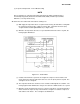
(2) Display Module.
The display module (Figure 4-16) consists of five digital displays and seven indicator lights.
The indicator lights include:
(a) Cool -- White LED: Energized when the refrigerant compressor is energized.
(b) Heat -- Orange LED: Energized to indicate heater operation in the heat or defrost mode.
(c) Defrost -- Orange LED: Energized when the unit is in the defrost mode.
(d) In-Range -- Green LED: Energized when the controlled temperature probe is within
specified tolerance of set point.
(e) Supply -- Yellow LED: Energized when the supply air probe is used for control. When
this LED is illuminated, the temperature displayed in the AIRTEMPERATURE display is
the reading at the supply air probe.