
Operating instructions


TM 11574A-OI
2-55
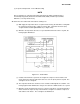
(3) Sequence Of Operation – Frozen Mode Cooling
NOTE
Prior to starting tests, verify that unit voltage (Function Code Cd07) is within tolerance
and unit amperage draw (Function Codes Cd04, Cd05, Cd06) is within expected limits.
Otherwise, tests may fail incorrectly.
All alarms must be rectified and cleared before starting tests.
(a) With supply air temperature above set point and decreasing, the unit will be cooling with
the condenser fan motor (CF), compressor motor (CH), evaporator fan motors (ES)
energized and the COOL light illuminated (see Figure 2-22).
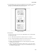
(b) When the air temperature decreases to a predetermined tolerance above set point, the
in-range light is illuminated.
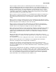
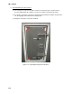
Figure 2-21. Frozen Mode.
(c) Contacts TC and TN are opened to de-energize the compressor and condenser fan
motors when the return air temperature decreases to 0.4 F (0.2 C) below set point. The
cool light is also de-energized.
(d) The evaporator fan motors continue to run to circulate air throughout the container. The
in-range light remains illuminated as long as the return air is within tolerance of set point.
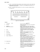
(e) When the return air temperature increases to 0.4 F (0.2 C) above set point and the three
minute off time has elapsed, relays TC and TN are energizes to restart the compressor
and condenser fan motors. The cool light is also illuminated.