
Operating instructions


TM 11574A-OI
2-51
e. Observe Unit Operations – Probe Check.
If the DataCORDER is off or in alarm mode, the controller will revert to a four probe configuration,
which includes the DataCORDER supply and return air probes as the secondary controller
probes. The controller continuously performs probe diagnosis testing, which compares the four
probes. If the probe diagnosis result indicates a probe problem exists, the controller will perform
a probe check to identify the probe(s) in error.
(1) Probe Diagnostic Logic – Standard If the probe check option (controller configuration code
CnF31) is configured for standard, the criteria used for comparison between the primary and
secondary control probes is:
1.8 F (1 C) for perishable set points or 3.6 F (2 C) for frozen set points.
If 25 or more of 30 readings taken within a 30minute period are outside of the limit, then a
defrost is initiated and a probe check is performed. In this configuration, a probe check will
be run as a part of every normal (time initiated) defrost.
(2) Probe Diagnostic Logic – Special If the probe check option is configured for special, the
above criteria are applicable. A defrost with probe check will be initiated if 25 of 30 readings
or 10 consecutive readings are outside of the limits In this configuration, a probe check will
not be run as a part of a normal defrost, but only as a part of a defrost initiated due to a
diagnostic reading outside of the limits.
(3) The 30 minute timer will be reset at each of the following conditions:
• At every power up
• At the end of every defrost
• After every diagnostic check that does not fall outside of the limits as outlined above.
(4) Probe Check:
A defrost cycle probe check is accomplished by energizing just the evaporator motors for
eight minutes at the end of the normal defrost. At the end of the eight minute period, the
probes will be compared to a set of predetermined limits. The defrost indicator will remain on
throughout this period.
Any probe(s) determined to be outside the limits will cause the appropriate alarm code(s) to
be displayed to identify the probe(s) that needs to be replaced. The P5 Pre-Trip test must be
run to inactivate alarms.
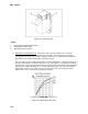
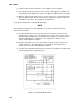
f. Sequence of Operation.
General operation sequences for cooling, heating, and defrost are provided in the following
subparagraphs. Schematic representation of controller action are provided in Figure 2-18 and
Figure 2-19. Refer to section 2-16 for detailed descriptions of special events and timers that are
incorporated by the controller in specific modes of operation.