
Operating instructions


TM 11574A-OI
2-34
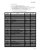
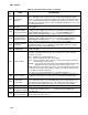
Table 2-7 Controller Alarm Indications - Continued
Code
No.
TITLE DESCRIPTION
ERROR DESCRIPTION
EER 1 – Program Memory Indicates a problem with the controller program.
EER 2 -- Watchdog
time-out
The controller program has entered a mode
whereby the controller program has stopped
executing.
EER 3 -- N/A N/A
EER 4 -- N/A N/A
EER 5 -- A-D failure
The Controller’s Analog to Digital (A-D) converter
has failed.
EER 6 -- IO Board failure Internal program/update failure.
EER 7 -- Controller failure Internal version/firmware incompatible.
EER 8--DataCorder failure Internal DataCorder memory failure.
EER -- 9 Controller failure Internal controller memory failure.
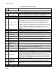
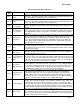
ERR #
Internal
Microprocessor
Failure
In the event that a failure occurs and the display cannot be updated, the status
LED will indicate the appropriate EER code using Morse code as shown below.
E R R 0 to 9ERR0 = . .--. .--. ----------
ERR1 = . .--. .--. . --------
ERR2 = . .--. .--. . . ------
ERR3 = . .--. .--. . . . ----
ERR4 = . .--. .--. . . . . --
ERR5 = . .--. .--. . . . . .
ERR6 = . .--. .--. -- . . . .
ERR7 = . .--. .--. ---- . . .
ERR8 = . .--. .--. ------ . .
ERR9 = . .--. .--. -------- .
Entr
StPt
Enter Setpoint
(Press Arrow &
Enter)
The controller is prompting the operator to enter a set point.
LO
Low Main Voltage
(Function Codes
Cd27-38 disabled
and NO alarm
stored.)
This message will be alternately displayed with the set point whenever the supply
voltage is less than 75% of its proper value.