
Operating instructions


TM 11574A-OI
2-29
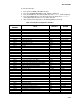
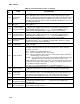
Table 2-6 Controller Function Codes - Continued
Code
No.
TITLE DESCRIPTION
Cd25
Compressor Run
Time Remaining
Until Defrost
This code displays the time remaining until the unit goes into defrost (in tenths of
an hour). This value is based on the actual accumulated compressor running
time.
Cd26
Defrost
Temperature
Sensor Reading
Defrost temperature sensor reading is displayed.
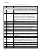
Configurable Functions
NOTE
Function codes Cd27 through Cd37 are user-selectable functions. The operator can
change the value of these functions to meet the operational needs of the container.
Cd27
Defrost Interval
(Hours or
Automatic)
There are two modes for defrost initiation, either user-selected timed intervals or
automatic control. The user-selected values are (OFF), 3, 6, 9, 12, or 24 hours
while the factory default is 12 hours. Automatic defrost starts with an initial
defrost at three hours and then adjusts the interval to the next defrost based on
the accumulation of ice on the evaporator coil. Following a start-up or after
termination of a defrost, the time will not begin counting down until the defrost
temperature sensor (DTS) reading falls below set point. If the reading of DTS
rises above set point any time during the timer count down, the interval is reset
and the countdown begins over. If DTS fails, alarm code AL60 is activated and
control switches over to the the return temperature sensor. The controller will act
in the same manner as with the DTS except the return temperature sensor
reading will be used. Defrost Interval Timer Value (Configuration variable
CnF23): If the software is configured to “SAv” (save) for this option, then the
value of the defrost interval timer will be saved at power down and restored at
power up. This option prevents short power interruptions from resetting an
almost expired defrost interval, and possibly delaying a needed defrost cycle.
NOTE
The defrost interval timer counts only during compressor run time.
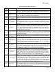
Cd28
Temperature Units
(Degrees C or
Degrees F)
This code determines the temperature units (C or F) which will be used for all
temperature displays. The user selects C or F by selecting function code Cd28
and pushing the ENTER key. The factory default value is Celsius units. NOTE
This function code will display “--------------“ if Configuration Variable CnF34 is set
to degrees F.
Cd29
Failure Action
(Mode)
If all of the control sensors are out of range (alarm code AL26) or there is a probe
circuit calibration failure (alarm code AL27), the unit will enter the shutdown state
defined by this setting. The user selects one of four possible actions as follows:
A -- Full Cooling (stepper motor SMV at maximum allowed opening)
B -- Partial Cooling (stepper motor SMV 11% open)
C -- Evaporator Fan Only
D -- Full System Shutdown -- Factory Default
Cd30
In-Range
Tolerance
The in-range tolerance will determine the band of temperatures around the set
point which will be designated as in-range. If the control temperature is in-range,
the in-range light will be illuminated. There are four possible values:
1 = +/- 0.9 F (+/- 0.5 C)
2 = +/- 1.8 F (+/- 1.0 C)
3 = +/- 2.7 F (+/- 1.5 C)
4 = +/- 3.6 F (+/- 2.0 C) -- Factory Default
Cd31
Stagger Start
Offset Time
(Seconds)
The stagger start offset time is the amount of time that the unit will delay at start-
up, thus allowing multiple units to stagger their control initiation when all units are
powered up together. The eight possible offset values are: 0 (Factory Default), 3,
6, 9, 12, 15, 18 or 21 seconds