
Operating instructions


TM 11574A-OI
2-24
During DataCORDER power-up, while using battery-pack power, the controller will
perform a hardware voltage check on the battery. If the hardware check passes, the
Controller will energize and perform a software battery voltage check before
DataCORDER logging. If either test fails, the real-time clock battery power-up will be
disabled until the next AC power cycle. Further DataCORDER temperature logging will
be prohibited until that time. An alarm will be generated when the battery voltage
transitions from good to bad indicating that the battery pack needs recharging. If the
alarm condition persists for more than 24 hours on continuous AC power, the battery
pack needs replacement.
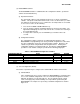
(9) Pre-Trip Data Recording.
The DataCORDER will record the initiation of a pre-trip test (refer to paragraph 2-15) and
the results of each of the tests included in pre-trip. The data is time-stamped and may be
extracted via the Data Retrieval program. Refer to Table 2-9 for a description of the data
stored in the DataCORDER for each corresponding pre-trip test.
(10) DataCORDER Communications.
Data retrieval from the DataCORDER can be accomplished by using one of the following;
DataReader, DataLine/DataView or a communications interface module.
NOTE
A DataReader, DataLine/DataView, or a communications interface module display of
Communication Failed is caused by faulty data transfer between the DataCORDER and
the data retrieval device. Common causes include:
1. Bad cable or connection between DataCORDER and data retrieval device.
2. PC communication port(s) unavailable or misassigned.
3. Chart Recorder Fuse (FCR) blown.
(a) DataReader
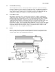
The Carrier Transicold Data Reader (see Figure 2-15) is a simple to operate hand
held device designed to extract data from the DataCORDER and then upload it to a
personal computer. The Data Reader has the ability to store multiple data files.
Refer to Data Retrieval manual 62-10629 for a more detailed explanation of the
DataReader.