
Operating instructions


TM 11574A-OI
2-23
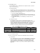
(4) Logging Interval (dCF03).
The user may configure four time intervals between data recordings. Data is logged at
exact intervals in accordance with the real-time clock. The clock is factory set at
Greenwich Mean Time.
(5) Thermistor Format (dCF04).
The user may configure the format in which the thermistor readings are recorded. The
low resolution is a 1 byte format and the normal resolution is a 2 byte format. The low
resolution requires less memory and records temperature in 0.45 F (0.25 C) increments
when in perishable mode or 0.9 F (0.5 C) increments when in the frozen mode. The
normal resolution records temperature in 0.01 degrees C (0.02 degrees F) increments for
the entire range.
(6) Sampling Type (dCF05 & dCF06).
Two types of data sampling are available –average and snapshot. When configured to
average, the average of readings taken every minute over the recording period is
recorded. When configured to snapshot, the sensor reading at the log interval time is
recorded.
(7) Alarm Configuration (dCF07 -- dCF10).
The cargo probe alarm may be configured to OFF, ON or AUTO. If a probe alarm is
configured to OFF, then the alarm for this probe is always disabled. If a probe alarm is
configured to ON, then the associated alarm is always enabled. If the probes are
configured to AUTO, they act as a group. This function is designed to assist users who
keep their DataCORDER configured, but do not install the probes for every trip. If all the
probes are disconnected, no alarms are activated. As soon as one of the probes is
installed, then all of the alarms are enabled and the remaining probes that are not
installed will give active alarm indications. The DataCORDER will record the initiation of
a pre-trip test (refer to paragraph 2-15) and the results of each of the tests included in
pre-trip. The data is time-stamped and may be extracted via the Data Retrieval program.
Refer to Table 2-9 for a description of the data stored in the DataCORDER for each
corresponding pre-trip test.
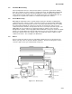
(8) DataCORDER Power-Up.
The DataCORDER may be powered up in any one of four ways:
1. Normal AC power: The DataCORDER is powered up when the unit is turned on via
the stop-start switch.
2. Controller DC battery pack power: If a battery pack is installed, the DataCORDER will
power up for communication when an interrogation cable is plugged into an
interrogation receptacle.
3. External DC battery pack power: A 12--volt battery pack may also be plugged into the
back of the interrogation cable, which is then plugged into an interrogation port. No
controller battery pack is required with this method.
4. Real-time Clock demand: If the DataCORDER is equipped with a charged battery
pack and AC power is not present, the DataCORDER will power up when the real-
time clock indicates that a data recording should take place. When the
DataCORDER is finished recording, it will power down.