
Operating instructions


TM 11574A-OI
2-21
(2) DataCORDER Software.
The DataCORDER Software is subdivided into the configuration software, operational
software and the Data Memory.
(a) Operational Software
The operational software reads and interprets inputs for use by the configuration
software. The inputs are labeled Function Codes. There are 35 functions (see Table
2-8), which the operator may access to examine the current input data or stored data.
To access these codes, do the following:
1. Press the ALT. MODE & CODE SELECT keys.
2. Press an arrow key until the left window displays the desired code number. The
right window will display the value of this item for five seconds before returning to
the normal display mode.
3. If a longer time is desired, press the ENTER key to extend the time to 30
seconds.
(b) Configuration Software
The configuration software controls the recording and alarm functions of the
DataCORDER. Reprogramming to the factory-installed configuration is achieved via
the same configuration card as the unit control module software. Changes to the
software may be made using the Data View integration device. A listing of the
configuration variables is provided in Table 2-2. Descriptions of DataCORDER
operation for each variable setting are provided in the following paragraphs.
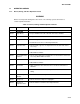
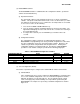
Table 2-3. DataCORDER Configuration Variables.
CONFIGURATION NO. TITLE DEFAULT OPTION
dCF01 (Future Use) -- --
dCF02 Sensor Configuration 2 2,5,6,9,54,64,94
dCF03 Logging Interval (Minutes) 60 15,30,60,120
dCF04 Thermistor Format Short Low, Normal
dCF05 Thermistor Sampling Type A A, b, C
(3) Sensor Configuration (dCF02).
Two modes of operation may be configured, the Standard Mode and the Generic Mode.
(a) Standard Mode
In the standard mode, the user may configure the DataCORDER to record data using
one of seven standard configurations. The seven standard configuration variables,
with their descriptions, are listed in Table 2-3. The six thermistor inputs (supply,
return, and cargo probe) and the humidity sensor input will be generated by the
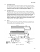
DataCORDER. An example of a report using a standard configuration is shown in
Figure 2-14.