
Operating instructions


TM 11574A-OI
2-14
II.
THEORY OF OPERATION
2-3. Theory Of Operation
The Large Field Refrigerated System (LFRS) is a climate controlled, insulated container system
comprised of an electrically powered refrigeration/freezing/heating unit and a 20-ft. ISO
compliant, insulated container.
2-4. 20 Foot Insulated Container
The insulated container is designed and built to the requirements of ISO 1496-2 standards. The
container is built to an 8 ft x 8 ft x 20 ft footprint, with eight reinforced corner fittings and a set of
double doors on one end with an emergency escape hatch. The interior of the container is a
“food grade” corrosion resistant, NSF approved stainless steel with aluminum T-grade floors that
assist in circulating airflow in and around the cargo to ensure uniform distribution of conditioned
air. The container floor is leak proof and has floor drains to provide complete drainage. An air
curtain is provided using removable, commercial grade, heavy-duty vinyl strips to block the
evaporator air exiting the container when the doors are open. Two lights are provided to
illuminate the interior of the container. Cargo restraints are provided on the floor and container
walls to secure cargo during transport. Foot holds and handles are affixed to the roof and
container doors to allow access to the roof. The container is painted with a military tan CARC
paint IAW MIL-DTL-53072. Forklift pockets are provided for transportation and markings
identifying the center of balance when empty are given to assist container transport.
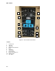
2-5. Refrigeration Unit
The RU removes heat from the container (refrigerates) using a vapor compression cycle which
uses the refrigerant R134a. The compressor compresses a low-pressure superheated vapor into
a high-pressure superheated vapor. This superheated vapor is then cooled in the condenser coil,
and is condensed and subcooled, thus leaving as a subcooled liquid and directed into the
receiver tank. The subcooled liquid refrigerant is first routed through the Suction Line Heat
Exchanger (SLHX), and then is expanded through the thermal expansion valve into the
evaporator as a low temperature saturated mixture. Heat is absorbed from the conditioned space
by heat transfer from the air to the evaporator coil. Heat is absorbed by the evaporated as
refrigerant absorbs latent heat and becomes a superheated vapor. After leaving the evaporator,
the refrigerant flows through the Suction Modulation Valve (SMV), which is a microlink-controlled
stepper motor, which modulates the refrigerant flow rate, and thus the RU cooling capacity.
Upon startup of the SMV will reset to a known open position. This is accomplished by assuming
the valve was fully open, driving it fully closed, resetting the percentage open to zero, then
opening to a known 21% staging position.
The RU is equipped with a Quench valve, which operates similarly to the TXV, and meters
refrigerant into the compressor suction port to cool the compressor during high temperature
operation.
A 3-way Liquid Service Valve, sometimes called a "King Valve", is located at the receiver tank,
but before the Filter/Drier, which allows a low-side pump down. This causes all of the refrigerant
to be pumped into the receiver tank, and allows for servicing of the Filter/Drier, SLHX, TXV, and
Evaporator. Refer to section 3-10.b paragraph 2b.
2-6. Perishable Mode Cooling
The controller monitors the supply air. When the supply air temperature increases to 0.4 F (0.2 C)
above the set point and the three minute off time has elapsed, relays are energized to restart the
compressor and condenser fan motors. Lights indicate when air is cooling or in-range.