
Operating instructions


TM 11574A-OI
2-10
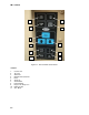
Table 2-1. Operating Controls and Indicators - Continued
Item No. Description Type Component Function
1 COOL (White LED) Electrical LED energized when refrigerant
compressor is energized.
2 Heat (Orange LED) Electrical LED energized when heater operation in
heat or defrost mode.
3 Defrost (Orange
LED)
Electrical LED energized when RU is in defrost
mode.
4 In-Range (Green
LED)
Electrical LED energized when the controller
temperature probe is within specified
tolerance set point.
5 Alarm (Red LED) Electrical LED energized when there is an active or
inactive shutdown alarm in the alarm
queue.
6 Supply (Yellow LED) Electrical LED energized when the supply air probe
is being used for control. When
illuminated, AIR TEMPERATURE
displays the reading at the supply air
probe.
7 Return (Yellow LED) Electrical LED energized when the return air probe
is being used for control. When
illuminated, AIR TEMPERATURE
displays the reading at the return air
probe.
8 SETPOINT/Code Electrical Displays set point value or controller
function codes.
9 AIR
TEMPERATURE/
Data
Electrical Displays air temperature at the supply
and return air probes or data value
indicated by function code display.