
Operating instructions


TM 11574A-OI
4-18
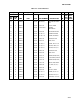
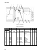
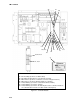
Figure 4-7. Controller Module.
1,2,3,4,7
30
8
14
15
16
18
19
5,6
22
21
20
10,11,12,13
11,13,17
9
NOT SHOWN
23 – Pin Assembly (Connects to ribbon cable)
24 – Kit, Battery Replacement (Located inside controller)
25 – Wire Harness (Connects controller to current sensing transformer)
26 – Wire Harness (Connects display module to controller)
27 – Label, Warning (Located on control box behind controller)
28 – Label, Warning (Located on shields)
29 – Label, Warning (Located on the bottom panel of the control box between
the communications interface module and the switch
p
anel
)