
Operating instructions


TO 11574A-OI
1-3
1-3. Physical Description and Specification Data
a. ISO Container.
The ISO container is a 20 ft long, 8 ft wide, 8 ft tall ISO certified insulated
container. Interior electrical lighting system is provided for low light conditions. Collapsible
access steps lead to the non-slip roof for easy safe access and an emergency escape hatch is
provided for emergency situations. Interior T-grade floors are installed to meet sanitary
requirements.
b. Refrigeration Unit.
The Refrigeration Unit is designed to maintain interior temperatures between
-22°F and 86°F using R-134A refrigerant. The refrigeration unit uses an advanced reciprocating
semi hermetic compressor, thermal expansion valve, suction modulation valve, refrigerant to air
heat exchangers, and a liquid reciever to provide heating and cooling capabilities. It features a
quick connect dual voltage transformer to provide either 190/230 volt or 380/460 volt 3 phase
50/60 Hz power. A microprocessor controller and integral data recorder are provided for state of
the art temperature control. A main power circuit breaker is provided to protect equipment from
damage.
c. Forklift Pockets.
Forklift pockets are provided for ease of installation and removal. There are two
forklift pockets provided on the front of the RU which are used to remove and install the RU into
the container. There are three forklift pockets on the sides of the container used for moving the
container.
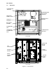
d. Refrigeration Unit - Front Section.
The front section of the refrigeration unit gives access to many
of the components that run the Large Field Refrigeration System. The unit model number, serial
number, and parts identification number can be found on the serial plate to the left of the
compressor.
e. Fresh Air Makeup Vent.
The purpose of the makeup air vent is to provide adequate ventilation for
the commodities that require fresh air circulation.
f. Evaporator Section.
The evaporator section houses all of the components that allow the
refrigerant to be changed from liquid to vapor. The evaporator section contains the return
temperature sensor, humidity sensor, thermostatic expansion valve, dual-speed evaporator fans
(EM1 and EM2), evaporator coil and heaters, defrost temperature sensor, heat termination
thermostat, and heat exchanger. The evaporator fans circulate air through the container by pulling
it in the top of the unit, directing it through the evaporator coil where it is heated or cooled, and
discharging it at the bottom. The evaporator components are accessible by removing the upper
rear panel.
g. Compressor Section.
The compressor section houses all of the components required to
compress the refrigerant, the power cable storage compartment and the autotransformer. The
compressor section includes the compressor (with high pressure switch), power cable storage
compartment, and autotransformer. This section also contains the suction modulating valve,
discharge pressure regulating valve, discharge temperature sensor, and discharge/suction
pressure transducers. The supply temperature sensor, supply recorder sensor, and ambient
sensor are located at the right side of the compressor. A three way valve is located after the
receiver which allows a low-side pump down.
h. Air-cooled Condenser Section.
The air-cooled condenser section consists of the condenser fan,
condenser coil, receiver with sight glass/moisture indicator, quench valve, manual liquid line valve,
filter-drier, condenser pressure transducer, and fusible plug. The condenser fan pulls air in
through the bottom of the coil and discharges it horizontally out through the condenser fan grille.
i. Control Box Section.
The control box houses the manual operation switches, circuit breaker (CB-
1), compressor, fan and heater contactors, control power transformer, fuses, keypad, display
module, current sensor module, and controller module. A document holder is located on the
inside of the control box door.