
Operating instructions


TM 11574A-OI
3-38
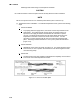
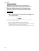
Slide large heat shrink tubing over both splices and shrink.
CAUTION
Do not allow moisture to enter wire splice area as this may affect the sensor resistance.
NOTE
The P5 Pre-Trip test must be run to inactivate probe alarms (refer to section 2-15).
(c) Temperature Sensor Installation. To install the temperature sensor, perform the following
steps:
1
Sensors STS/SRS
a
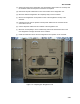
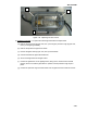
To properly position a supply sensor, the sensor must be fully inserted into the
probe holder. This positioning will give the sensor the optimum amount of
exposure to the supply air stream, and will allow the Controller to operate
correctly. Insufficient probe insertion into the probe holder will result in poor
temperature control due to the lack of air flow over the sensor. It is also
necessary to ensure that the probe tip does not contact the evaporator back
panel. The design minimum clearance of 1/4 in (6 mm) should be maintained
(Figure 3-19).
2
Sensor RTS/RRS
a
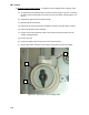
Reinstall the return sensor as shown in Figure 3-18. For proper placement of the
return sensor, be sure to position the seal section of the sensor against the side
of the mounting clamp.
3
Sensor DTS
a
The DTS sensor must have insulating material placed completely over the sensor
to insure the coil metal temperature is sensed.
Figure 3-17. Sensor and Cable Splice