
Operating instructions


TM 11574A-OI
3-37
3
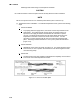
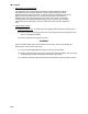
If required, prepare the replacement sensor by cutting sensor wire(s) back 1-/2 in
(140 mm). For 3-wire sensors, the black wire should be cut at the middle length and
the red/white wire cut to the shorter length (Figure 3-17).
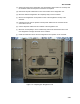
Figure 3-16. Sensor Types
4
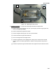
Prepare the cables by cutting wires to the opposite of the sensor (Figure 3-18).
NOTE
When installing a single wire color two wire sensor, cut one wire of existing two wire cables 1-1/2
in (40 mm) shorter than the other wire.
When replacing two single sensors with a combination (3-wire) sensor, the black wires of the
cables should be cut to the same length and the red wire of one cable cut to the shorter length.
When replacing an original 3-wire sensor, cut the black wire to the middle length and the red wire
to the shorter length.
5
Strip back insulation on all wiring 1/4 in (6.3 mm).
6
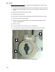
Slide a large piece of heat shrink tubing over the cable, and place small pieces of
heat shrink tubing, one over each wire, before adding crimp fittings as shown in
Figure 3-18.
7
If required, slide the cap and grommet assembly onto the replacement sensor. If the
replacement sensor is of a larger diameter than the original, a different grommet may
be required.
8
Slip crimp fittings over dressed wires (keeping wire colors together). Make sure wires
are pushed into crimp fittings as far as possible and crimp with crimping tool.
9
Solder spliced wires with a 60% tin and 40% lead Rosin core solder.
10
Slide heat shrink tubing over splice so that ends of tubing cover both ends of crimp
as shown in Figure 3-18.
11
Heat tubing to shrink over splice. Make sure all seams are sealed tightly against the
wiring to prevent moisture seepage.