
Operating instructions


TM 11574A-OI
3-36
(19) Temperature Sensor Test
(a) Temperature Sensor Test. To check the temperature sensor, perform the following
steps:
1
Remove the sensor and place in a 32 F (0 C) ice-water bath. The ice-water bath is
prepared by filling an insulated container (of sufficient size to completely immerse
bulb) with ice cubes or chipped ice, then filling voids between ice with water and
agitating until mixture reaches 32 F (0 C) measured on a laboratory thermometer.
2
Start unit and check sensor reading on the control panel. The reading should be 32
F (0 C). If the reading is correct, reinstall sensor; if it is not, continue with the
following:
a
Turn unit OFF and disconnect power supply.
b
Refer to paragraph 3-10b(17) and remove controller to gain access to the sensor
plugs.
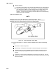
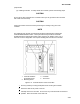
c
Using the plug connector marked “EC,” that is connected to the back of the
controller, locate the sensor wires (RRS, RTS, SRS, STS, AMBS, DTS, CPDS
ORCPSS as required). Follow those wires to the connector and using the pins of
the plug, measure the resistance. Values are provided in Figure 3-16.
Figure 3-15. Sensor Temperature/Resistance Chart.
NOTE
Due to the variations and inaccuracies in ohmmeters, thermometers, or other test
equipment, a reading within 2% of the chart value would indicate a good sensor. If a
sensor is defective, the resistance reading will usually be much higher or lower than the
resistance values given.
(b) Temperature Sensor Removal. To remove the temperature sensor, perform the following
steps:
1
Turn unit power OFF and disconnect power supply.
2
For two wire sensors, cut cable 2 in (5 cm) from shoulder of defective sensor and
discard the defective sensor only. For 3-wire sensors, cut at 9 in (23 cm). Slide the
cap and grommet off well mounted sensor and save for possible reuse. Do not cut
the grommet.