
Operating instructions


TM 11574A-OI
3-35
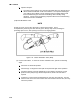
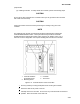
(b) Removing the Controller. To remove the controller, perform the following steps:
1
Disconnect all front wire harness connectors and move wiring out of way.
2
The lower controller mounting is slotted. Loosen the top mounting screw (Figure 3-
15) and lift up and out.
3
Disconnect the two back connectors (EC) and remove module.
4
When removing the replacement controller from its packaging, note how it is
packaged. When returning the old controller for service, place it in the packaging in
the same manner as the replacement. The packaging has been designed to protect
the controller from both physical and electrostatic discharge damage during storage
and transit.
(c) Installing the Controller. To install the controller, perform the following steps:
1
Connect the two back connectors (EC). Torque the connectors to 10 inch pounds
(0.12 mkg).
2
Position the module into the slot and tighten the screws. Torque the mounting screws
to 20 inch pound (0.23 mkg)
3
Connect all front wire harness connectors to the module.
(d) Removing Heat Termination Thermostat. This maintenance procedure does not exist in
the commercial manual. It is to be developed at a later date.
(e) Replacing Heat Termination Thermostat. This maintenance procedure does not exist in
the commercial manual. It is to be developed at a later date.