
Operating instructions


TM 11574A-OI
3-34
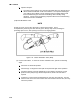
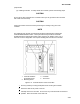
Controller Troubleshooting. A group of test points (TP) (Figure 3-15) are provided on
the controller for troubleshooting electrical circuits (schematic diagram, Appendix A).
A description of the test points follows:
NOTE
Use a digital voltmeter to measure AC voltage between TPs and ground (TP9), except for
TP8.
1 TP2 This test point enables the user to check if the internal protector for the
compressor motor (IP-CP) or high pressure switch is open.
2
TP3 This test point enables the user to check if the water pressure switch (WP)
contact is open or closed.
3
TP 4 This test point enables the user to check if the internal protector for the
condenser fan motor (IP-CM) is open or closed.
4
TP 5 This test point enables the user to check if the internal protectors for the
evaporator fan motors (IP-EM1 or IP-EM2) are open or closed.
5
TP 6 This test point enables the user to check if the controller water tank heater
relay (TQ) is open or closed.
6
TP 7 This test point is not used in this application.
7
TP 8 This test point is not applicable to the units covered herein.
8
TP 9 This test point is the chassis (unit frame) ground connection.
9
TP 10 This test point enables the user to check if the heat termination thermostat
(HTT) contact is open or closed. 4.3.20.3 Controller Programming Procedure