
Operating instructions


TM 11574A-OI
3-30
(15) Checking the Stepper Valve.
(a) Checking with ohmmeter
1
Disconnect the 4-pin connector to the stepper SMV. With a reliable digital ohmmeter,
check the winding resistance. In normal ambient, the valve should have 72 to 84
ohms measured on the red/green (a-b terminals) and on the white/black (c-d
terminals) leads. If an infinite or zero reading occurs, check connections and replace
the motor. If near normal or normal reading occurs, proceed to step 3-10b(14)(d) to
check out the controller.
(b) Check Operation Stepper Valve. To check the operation of the stepper valve, perform
the following steps:
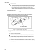
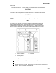
1
Stop the unit, disconnect the 4-pin connector from the stepper module to the valve
(Figure 3-13) and attach the SMA-12 stepper drive to the connector going to the
valve.
2
Set the SMA-12 pulse per second (PPS) to one PPS and either open or close valve.
Each LED should light sequentially until all four are lit. Any LED failing to light
indicates an open on that leg, which indicates a poor connection or an open coil.
Repair or replace as required to achieve proper operation.
3
Restart unit, set the step rate to 200PPS on SMA-12 for the valve, and close stepper
valve while watching the suction gauge. Within one minute the suction pressure will
go into a vacuum. This is an indication that the valve is moving.
4
If no change in suction pressure is detected, check for resistance (refer to 3-
10b(14)(a)), and check connections for proper continuity and retest. If the valve is
functioning, and all connections and motor resistance are good, check the drive
module (refer to 3-10b(13)(a)).
5
If the valve is determined to be faulty after completing the above steps, perform a low
side pump down. Remove valve power head assembly, and replace with a NEW
valve power head assembly, torque nut to 35 ft-lb, evacuate low side, and open all
service valves.
CAUTION
DO NOT disassemble piston from NEW suction modulating valve power head assembly.
Doing so may result in damage to piston.
(c) Checking the Controller. To check the controller, perform the following steps:
1
Turn unit OFF.
2
With voltmeter set to read 20 volts DC, attach the positive lead to MC1 of the 4-pin
connector and the negative lead to the TP9. Turn ON unit and watch the volt meter.
After a short delay, the reading should remain unchanged at 0 volts. If 5 VDC, check
jumper wire form MC1 to MC8 is in place; if not, install and retest.