
Operating instructions


TM 11574A-OI
3-21
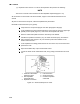
NOTE
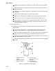
TXV Bulb Clamp is soldered to the suction line.
1. Suction Line 4. TXV Bulb
2. Thumbscrew 5. Foam Insulation
3. TXV Bulb Clamp
Figure 3-8. Thermostatic Expansion Valve Bulb.
(b) Checking Superheat. To check the superheat function of the thermostatic expansion
valve perform the following:
NOTE
Proper superheat measurement should be completed at 0 F (-17.8 C) container box
temperature where possible.
1
Open the upper right Evaporator Fan Motor (EFM#1) access panel (Figure 2-1) to
expose the expansion valve.
2
Attach a temperature sensor near the expansion valve bulb and insulate. Make sure
the suction line is clean and that firm contact is made with the sensor.
3
Connect an accurate gauge to the service port directly upstream of the suction
modulating valve.
4
Set the temperature set point to 0 F (-17.8 C) and run unit until conditions stabilize.
5
The readings may cycle from a high to a low reading. Take readings of temperature
and pressure every three to five minutes for a total of 5 or 6 readings.
6
From the temperature/pressure chart (Table 3-8), determine the saturation
temperature corresponding to the evaporator outlet test pressures at the suction
modulation valve.
7
Subtract the saturation temperatures determined in step 6 from the temperatures
measured in step 5
. The difference is the superheat of the suction gas. Determine
the average superheat. It should be 8 to 12 F (4.5 to 6.7 C).