
Operating instructions


TM 11574A-OI
3-20
1
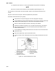
Open condenser fan screen guard.
2
Loosen two square head set screws on fan (thread sealer has been applied to set
screws at installation). Disconnect wiring from motor junction box.
CAUTION
Take necessary steps (place plywood over coil or use sling on motor) to prevent motor
from falling into condenser coil.
3
Remove motor mounting hardware and replace the motor. It is recommended that
new locknuts be used when replacing motor. Connect wiring per wiring diagram.
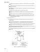
4
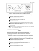
Install fan loosely on motor shaft (hub side in). DO NOT USE FORCE. If necessary,
tap the hub only, not the hub nuts or bolts. Install venturi. Apply “Loctite” to fan set
screws. Adjust fan within venturi so that the outer edge of the fan projects 3/16 to 1/8
in (3.2 to 6.4 mm) back from edge of the venturi. Spin fan by hand to check
clearance.
5
Close and secure condenser fan screen guard.
6
Apply power to unit and check fan rotation. If fan motor rotates backward, reverse
wire numbers 5 and 8.
(b) Condenser Pressure Transducer Inspection. This maintenance procedure does not exist
in the commercial manual. It is to be developed at a later date.
(c) Remove Condenser Pressure Transducer. This maintenance procedure does not exist in
the commercial manual. It is to be developed at a later date.
(d) Replace Condenser Pressure Transducer. This maintenance procedure does not exist in
the commercial manual. It is to be developed at a later date.
(9) Filter Drier.
(a) To replace filter-drier perform the following steps:
1
Pump down the unit (refer to Pumping the unit down paragraph 3-10b(2)(d)) and
replace filter-drier.
2
Evacuate the low side in accordance with Evacuation and dehydration paragraph 3-
10b(3).
3
After unit is in operation, inspect for moisture in system and check charge.
(10) Thermostatic Expansion Valve.
(a) The thermostatic expansion valve (Figure 3-9) is an automatic device that maintains
constant superheat of the refrigerant gas leaving the evaporator, regardless of suction
pressure. The function of the thermostatic expansion valve is:
1
Automatic control of the refrigerant flow to match the evaporator load.
2
Prevention of liquid refrigerant entering the compressor. Unless the valve is
defective, it seldom requires maintenance other than periodic inspection to ensure
that the thermal bulb is tightly secured and properly insulated (Figure 3-9).