
Operating instructions


TM 11574A-OI
3-14
3
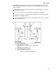
Fully open (backseat) the suction service valve and remove the service port cap.
4
Connect charging line between suction service valve port and cylinder of refrigerant
R-134a. Open VAPOR valve.
5
Partially front seat (turn clockwise) the suction service valve and slowly add charge
until the refrigerant appears at the proper level.
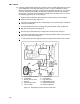
(5) Compressor.
WARNING
Make sure power to the unit is OFF and power plug disconnected before replacing the
compressor.
(a) There are several points that must be covered prior to performing any maintenance on
the compressor, those points are as follows:
1
The compressor should not operate in a vacuum greater than 500 mm/hg (20
inches/hg).
2
The service replacement compressor is sold without shutoff valves (but with valve
pads), and without terminal box and cover. Customer should retain the original
terminal box, cover, and high pressure switch for use on replacement compressor.
3
Check oil level in service replacement compressor (refer to Compressor oil level
paragraph 3-10b(5)(e)).
4
A compressor terminal wiring kit must be ordered as a separate item when ordering
replacement compressor. Appropriate installation instructions are included with kit.
5
Refer to Table 3-8 for charts on compressor pressure, temperature and Figure 3-21
for motor current curves.
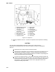
(b) Removal and replacement of the compressor. To remove and replace the compressor
perform the following steps:
1
Remove the protective guard from lower section of the unit.
2
Pump down low side (refer to Pumping the unit down paragraph 3-10b(2)(d)) or front
seat compressor service valves and remove refrigerant from compressor using a
refrigerant recovery system.
3
Locate the compressor junction box. Tag and disconnect wiring from compressor
terminals and remove compressor junction box.
4
Loosen service valve mounting bolts, break seal, and then remove bolts.
5
Remove compressor plate mounting bolts.