
Operating instructions


TM 11574A-OI
3-12
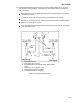
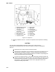
1. Reclaimer 6. Liquid Service Valve
2. Discharge Service Valve 7. Vacuum Pump
3. Compressor 8. Electronic Vacuum
4. Suction Service Valve Gauge
5. Receiver or Condenser 9. Manifold Gauge Set
Refrigerant Cylinder
Figure 3-5. Compressor Service Connections.
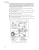
(c) Partial system procedure. To perform a partial evacuation and dehydration cycle on the
complete refrigeration system, follow the steps below:
1
If the refrigerant charge has been removed from the compressor for service,
evacuate only the compressor by connecting the evacuation set-up at the
compressor service valves. Follow evacuation procedures of the preceding
paragraph except leave compressor service valves front seated until evacuation is
completed.
2
If refrigerant charge has been removed from the low side only, evacuate the low side
by connecting the evacuation set-up at the compressor service valves and liquid
service valve except leave the service valves front seated until evacuation is
completed.
3
Once evacuation has been completed and the pump has been isolated, fully open
(backseat) the service valves to isolate the service connections and then continue
with checking and, if required, adding refrigerant in accordance with normal
procedures.