
User's Manual


MHX 910A Operating Manual: Chapter3 Installation 7
3. Installation
3.0 Overview
The installation, removal or maintenance of all antenna
components must be carried out by qualified and
experienced personnel.
The MHX-910A complies with FCC part 15 at the modular level for
operation in the license-free 902-928 MHz ISM band. This chapter provides
guidelines for installing and deploying equipment which incorporates the
MHX-910A module.
3.1 Estimating the Gain Margin
Successful communication between MHX-910A modules is dependent on
three main factors:
• System Gain
• Path Loss
• Interference
System gain is a calculation in dB describing the performance to be expected
between a transmitter-receiver pair. The number can be calculated based on
knowledge of the equipment being deployed. The following four factors
make up a system gain calculation:
1. Transmitter power (user selectable 0, 20 to 30dBm)
2. Transmitter gain (transmitting antenna gain minus cabling loss between
the transmitting antenna and the MHX-910A module)
3. Receiver gain (Receiving antenna gain minus cabling loss between the
receiving antenna and the module)
4. Receiver sensitivity (Specified as -105dBm on the MHX-910A module)
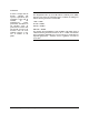
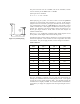
In the following illustration, the transmitting antenna has a gain of 6 dB, and
the receiving antenna has a gain of 3 dB. The cable loss between the module
and the antenna is 2 dB on both the transmitting and receiving side.
Figure 1 Gain Calculation
Transmitter
30 dBm
Output Power
Receiver
Sensitivity =
-105 dBm
Cable Loss = 2 dBCable Loss = 2 dB
Antenna Gain = 6 dB
Antenna Gain = 3 dB