microHAM © 2006 All rights reserved DIGI KEYER microHAM fax. +421 2 4594 5100 e-mail : support@microham.com homepage : www.microham.com Release 1.
microHAM © 2006 All rights reserved TABLE OF CONTENTS CHAPTER PAGE 1. 2. 3. 4. WARRANTY .................................................................................................................................... 3 PACKACE CONTESTS ................................................................................................................... 3 IMPORTANT WARNINGS ............................................................................................................... 3 INSTALLATION ....
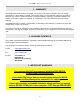
microHAM © 2006 All rights reserved 1 - WARRANTY microHAM warrants this product for 3 years. The product must not be modified in any way, except configuration or the warranty is voided. The warranty does not cover damage caused by improper or abnormal use, failure to follow instructions, improper installation, lightning, or excessive voltage. The product will be either repaired or replaced, at our discretion. The only cost will be the cost of return shipping.
microHAM © 2006 All rights reserved 4 - INSTALLATION Installing DIGI KEYER consists of several steps: 1) preparing DIGI KEYER to work with your radio 2) installing microHAM USB Device Router (the control and interface software) 3) installing the USB drivers 4) configuring the Windows USB Audio Device 5) configuring Router Preparing DIGI KEYER for Use 1. Remove the top cover from the DIGI KEYER and set the CAT jumpers as shown in the following chart.
microHAM © 2006 All rights reserved Installing microHAM USB Device Router To install Router click on the Install USB Device Router link on the installation CD or download the most recent installation package from the microHAM web site: www.microHAM.com/downloads.html. If you download an updated package, click on "urouter_release_xx_xx.exe" (xx_xx is version) to start the installation. The Windows setup utility will start and ask into which folder Router and its supporting files should be installed.
microHAM © 2006 All rights reserved Installing the USB DRIVER Connect the USB cable to the DIGI KEYER USB jack, plug the other end of the USB cable into an open USB port in your computer. The automatic Wizard will appear, insert the installation CD into the CDROM drive and select "No, not this time" when asked to connect to Windows Update. Then click "Next." Now, click Install from specific location and use the path to the Router installation directory.
microHAM © 2006 All rights reserved Configuring the USB Audio CODEC Windows will automatically install the USB Audio Device driver to support the USB Audio CODEC in DIGI KEYER. Windows automatically selects any newly installed Audio Device as the default device for Sound Playback and Sound recording.
microHAM © 2006 All rights reserved Configuring the microHAM USB Device Router The MicroHAM USB Device Router (Router) program provides a Windows compatible configuration tool for microHAM USB Devices (DIGI KEYER as well as microKEYER, CW Keyer and USB Interfaces) and software interface to other Windows applications (loggers, digital mode software, etc.). The software interface is provided as Virtual Serial Ports.
microHAM © 2006 All rights reserved Creating and Using Virtual Serial Ports microHAM Router provides a set of virtual serial ports which allow Windows applications (loggers and digital software) to work with DIGI KEYER just as they would work with "real" (hardware) serial ports. In order to use these virtual Ports, you must first define the virtual ports and then assign each function (radio control, PTT, CW, FSK, etc.) to a virtual port.
microHAM © 2006 All rights reserved 5 PANEL DESCRIPTION All connectors for connecting the computer, radio and accessories are located on the rear panel. Rear Panel (1) – PA PTT: PTT output for Power Amplifier Ground during transmit TIP - Signal SHELL - Ground (2) - LNA PTT: Control output for Low Noise Amplifier Ground during transmit TIP - Signal SHELL - Ground If the jumper is in SS position, open collector switching transistor is connected to the PAPTT or LNAPTT output jack.
microHAM © 2006 All rights reserved Front Panel (1) – POWER YELLOW color indicates when unit is powered (2) – TX Adjusts transmit audio level (drive) (3) – CW/FSK RED color indicates when CW is active, GREEN indicates when FSK is active (4) – SQL GREEN color indicates when squelch is active (5) – PTT RED color indicates when PTT is active (6) – RX #2 Adjusts receive audio level from the second (sub-, aux-, etc.) receive channel. (7) – RX #1 Adjusts receive audio level from the main receive channel.
microHAM © 2006 All rights reserved 6. microHAM USB DEVICE ROUTER General Router settings can be invoked by clicking on Router main menu. ROUTER MENU Restore Router Settings: used to restore settings from a urs file created by the backup command. Restoring a backup will delete all current Router settings including presets, use it carefully! A urs file can be used only on the system which generated the file (the file contains the unit serial number) and a computer with same port assignments.
microHAM © 2006 All rights reserved PRESET MENU The requirements of each application (logging, control and digital mode programs) are different and each program handles radio control, CW / FSK/PTT keying, and the sound card its own way. In some instances what will work for one application may not work properly with another. To get maximum performance from DIGI KEYER, you may wish to customise the settings for each application.
microHAM © 2006 All rights reserved DEVICE MENU Router can control several devices. This allows configuring the settings for all connected devices at one time by using the Presets described in 6.2 Each device has its own tab (page) in the main Router notebook. The content of a device tab depends on device type. Adding a device is automatic the first time Router detects a supported device (USB driver). Once detected, a device remains in Router even though device is disconnected.
microHAM © 2006 All rights reserved VIRTUAL PORT MENU It is necessary to create several virtual serial ports (COM ports) in order for a Windows application (logging, control or digital mode program) to access microHAM devices. By using templates, the neccessary virtual ports are created automatically. However, virtual ports can also be created manually. Create - Creates virtual COM ports. It is possible to select more ports at once by holding Ctrl key on keyboard and clicking on COM port numbers.
microHAM © 2006 All rights reserved HELP MENU microHAM Home Page - Link to www.microHAM.com microHAM Downloads page - Link for downloading the current software and firmware updates Show Tooltips - When checked, small, single line help is displayed below the mouse cursor About - Shows the version number DEVICE CONFIGURATION TABS There are three (3) tabs for configuring DIGI KEYER. Each tab controls a part of DIGI KEYER's functions. Any change to the first two (2) tabs are applied immediately to DIGI KEYER.
microHAM © 2006 All rights reserved CONTROL PORT The control channel is used by the host application to control transceiver frequency, mode, T/R switching and many other parameters. The application communicates with the radio using a serial protocol. Most modern radios implement some form of serial control but almost every radio implementation is different. The amount of radio control depends on the particular application and radio.
microHAM © 2006 All rights reserved The microphone gain control then becomes a form of transmit power control. An initial indication of proper audio drive level can be seen on the ALC meter of the radio. Provided that there is NO audio processing in circuit and that the microphone gain control is in its normal operating position, then, if the ALC does not show or just starts to indicate during transmission, the signal is likely to be clean.
microHAM © 2006 All rights reserved CW Port By their very nature, USB ports are not well suited to transfer the real time events required for CW keying on virtual serial port control signals (DTR). In addition to the latency in USB, there are also latencies caused by computer CPU load, internal Windows message processing (inter-process communication) and data flow from another peripherals using the USB ports. This can result in transmitted characters being garbled.
microHAM © 2006 All rights reserved TIP: Always use serial PTT instead of the radio command PTT or VOX. It is the only sure way to assure proper sequencing of an LNA and Power Amplifier. To test basic operation of the PTT from the computer to the radio, click on the Test button with no port addigned orthe port closed. More details about function check are described in chapter 12.2 2nd PTT Port The second PTT channel is identical to the primary PTT channel.
microHAM © 2006 All rights reserved KEYING TAB The Keying tab includes controls for the USB Audio processor, PTT and FSK Keyboard. USB Audio The sound card configuration depends on the capability of your application software. Some software can directly drive the sound mixer controls. Transmit Level: sets the level of the audio output from the digital to analog converter.
microHAM © 2006 All rights reserved PTT – T/R KEYING DIGI KEYER has three (3) PTT outputs: PTT, PA PTT and LNA PTT. PTT is brought out to the DB15 Radio Port. PA PTT and LNA PTT are available on RCA connectors at the DIGI KEYER rear panel. PTT is normally wired to the radio Accessory jack and is used to switch the radio into transmit. PA PTT is present at the DIGI KEYER rear panel RCA jack and is designed for switching a power amplifier. PA PTT is enabled by checking the PA PTT box.
microHAM © 2006 All rights reserved FSK MESSAGES TAB On this tab you can define nine messages of up to 50 characters each which are stored in DIGI KEYER's non-volitile memory. Each memory may have a programmable repeat delay and/or call another memory. Commands which may be included in a memory are: Set PTT: Clear PTT: CR & LF: close PTT. release PTT.
microHAM © 2006 All rights reserved 7 - EXTERNAL KEYBOARD DIGI KEYER allows generating FSK signals from a PS2 keyboard attached to the Remote jack. TIP: The keyboard must be PS/2. A USB keyboard with PS/2 adapter will not function properly.
microHAM © 2006 All rights reserved 8 - FUNCTION CHECK Basic operation can be checked with the Test buttons, located on Ports tab. FSK - test button sends ten (10) RY characters at 45.45 5/N/1.5 to the MK FSK output. The green arrow on the Ports tab and the green FSK LED on the DIGI KEYER front panel should blink together . If the PTT box is checked, the characters will be transmitted. 2nd FSK - test button sends ten (10) RY characters at 45.45 5/N/1.5 to the MK FSK output.
microHAM © 2006 All rights reserved 9 - SPECIFICATIONS DIGI KEYER is a multi-mode interface between computer and transceiver. It has been optimized for amateur digital modes and includes a high performance USB sound processor. DIGI KEYER is connected to the computer using a single A-B USB cable which is included. The transceiver and DIGI KEYER are connected by single radio cable terminated on one side by a DB15M and on the other side by the appropriate plugs for the specific transceiver model.
microHAM © 2006 All rights reserved Hardware Specifications USB: USB 2.0 Full speed , USB 1.1 compatible Power consumption: USB – less than 100mA; Transceiver – less than 200mA at 13.8V (max. 16V) Radio Port: RxD, TxD – max. 57,600 Baud Levels: Jumpers selectable TTL, inverted TTL, open collector bus, RS232 CW: open collector, max 30V/400mA FSK: open collector, max 30V/400mA PTT: open collector, max 30V/400mA Audio Out: 600 Ohm, 3V p-p max. 3dB bandwidth: 0.
microHAM © 2006 All rights reserved 10 - FEATURES AND FUNCTIONS No Serial or Parallel port necessary, just one USB port Complete "Computer <-> Radio" galvanic isolation • bidirectional transformer isolation of audio signals • optical isolation of ALL digital signals -> Radio Control, CW, PTT, FSK Internal USB sound capability • Wide range audio level: works with transceiver levels from 100 mV to 1.5 V • Extremely low noise floor: as low as 0.
microHAM © 2006 All rights reserved APPENDIX A – DB15 RADIO CONNECTOR Pin # Label Description 1 Power +13.
microHAM © 2006 All rights reserved APPENDIX B – APPLE OS 10 INSTALLATION 1) To Install DIGI KEYER in Apple's OS 10 prepare the DIGI KEYER as for your radio as shown on Page 4. 2) Copy the FTDI USB Driver disk image (.dmg) to your desktop by clicking on the “Install microHAM Port Driver for Macintosh OS 10.0 – 10.39” or “Install microHAM Port Driver for Macintosh OS 10.4+” link from the supplied CD or download the most recent driver package from the microHAM web site: www.microHAM.com/downloads.