microHAM © 2008 All rights reserved DigiKeyer microHAM fax: +421 2 4594 5100 e-mail: support@microham.com homepage: www.microham.com Version 7.
microHAM © 2008 All rights reserved TABLE OF CONTENTS CHAPTER PAGE 1. FEATURES AND FUNCTIONS ................................................................................................... 3 2. IMPORTANT WARNINGS .......................................................................................................... 3 3. PANEL DESCRIPTION ............................................................................................................... 4 Front Panel ....................................
microHAM © 2008 All rights reserved 1 - FEATURES AND FUNCTIONS No Serial or Parallel port necessary, just one USB port Complete "Computer <-> Radio" isolation • bidirectional transformer isolation of audio signals • optical isolation of ALL digital signals: Radio Control, CW, PTT, FSK Internal USB sound capability • Wide range audio level: works with transceiver levels from 100 mV to 1.5 V • Extremely low noise floor: as low as 0.
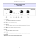
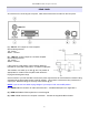
microHAM © 2008 All rights reserved 3 - PANEL DESCRIPTION FRONT PANEL (1) – POWER YELLOW color indicates when unit is powered (2) – TX Adjusts transmit audio level (drive) (3) – CW/FSK RED color indicates when CW is active, GREEN indicates when FSK is active (4) – SQL GREEN color indicates when squelch is active (5) – PTT RED color indicates when PTT is active (6) – RX #2 Adjusts receive audio level from the second (sub-, aux-, etc.) receive channel.
microHAM © 2008 All rights reserved REAR PANEL All connectors for connecting the computer, radio and accessories are located on the rear panel. (1) – PA PTT: PTT output for Power Amplifier Ground during transmit TIP - Signal SHELL - Ground (2) - LNA PTT: Control output for Low Noise Amplifier Ground during transmit TIP - Signal SHELL - Ground If the jumper is in SS position, open collector switching transistor is connected to the PAPTT or LNAPTT output jack. The transistor can switch up to 48V @ .8A.
microHAM © 2008 All rights reserved 4 - INSTALLATION Installing DIGI KEYER consists of several steps: 1) prepare DIGI KEYER to work with your radio 2) install microHAM USB Device Router (the control and interface software) 3) configure the Windows USB Audio Device 4) configure Router Preparing DigiKeyer for Use 1. Remove the top cover from the DIGI KEYER and set the CAT jumpers as shown in the following chart. The CAT interface jumpers must be configured to select the proper level for each radio type.
microHAM © 2008 All rights reserved Installing microHAM USB Device Router To install Router click on the Install USB Device Router link on the installation CD or download the most recent installation package from the web site: www.microHAM.com/downloads.html. If you download an updated package, click on "urouter_release_xx_xx.exe" (xx_xx is version) to start the installation. The Windows setup utility will start and ask into which folder Router and its supporting files should be installed.
microHAM © 2008 All rights reserved Configuring USB Audio CODEC Windows will automatically install the USB Audio Device driver to support the USB Audio CODEC in DIGI KEYER. Windows automatically selects any newly installed audio device as the default device for Sound Playback and Sound recording.
microHAM © 2008 All rights reserved Configuring microHAM USB Device Router The MicroHAM USB Device Router (Router) program provides a Windows compatible configuration tool for microHAM USB Devices (DIGI KEYER as well as microKEYER, CW Keyer and USB Interfaces) and software interface to other Windows applications (loggers, digital mode software, etc.). The software interface is provided as Virtual Serial Ports.
microHAM © 2008 All rights reserved Creating and Using Virtual Serial Ports microHAM Router provides a set of virtual serial ports which allow Windows applications (loggers and digital software) to work with DIGI KEYER just as they would work with "real" (hardware) serial ports. In order to use these virtual Ports, you must first create the ports and then assign a function (radio control, PTT, CW, FSK, etc.) to each virtual port.
microHAM © 2008 All rights reserved 5. microHAM USB DEVICE ROUTER ROUTER MENU Restore Router Settings: used to restore settings from a urs file created by the backup command. A urs file can be used only with the device for which it was generated (the file contains the unit serial number) on a computer with same port assignments. WARNING: Restoring a backup replaces all current Router settings including presets, use it carefully! Backup Router Settings: used to create backup urs file.
microHAM © 2008 All rights reserved Minimize: Clicking this will minimize Router to the system tray at the bottom right corner of the Windows Taskbar (the "System Notification Area"). TIP: When Router is minimized you can restore it by double-clicking on the Router tray icon. You can also restore Router by double-clicking on the Router icon on the desktop or restarting Router from the Programs menu. Exit: Clicking on this item will terminate Router.
microHAM © 2008 All rights reserved 3. By right clicking on the system tray icon when the Router is minimized. The presets and the current router configuration are stored to the registry when Router is closed and recalled when Router is loaded. Save as - Saves the current Router settings to a preset for future use. Rename - Allows renaming of an existing preset. Delete - Delete chosen preset. Show buttons - When checked, Router shows the preset buttons. DEVICE MENU Router can control several devices.
microHAM © 2008 All rights reserved TIP: Templates are a powerful tool for quickly configuring Router to work with a particular application. Template files are interchangeable between computers and are well suited for cloning setups when using the same application in multi-computer stations or for sharing custom setups between users. Upload Firmware: microHAM will occasionally release updates to the firmware in DigiKeyer. The update may support news feature in Router or improve application compatibility.
microHAM © 2008 All rights reserved HELP MENU Manuals: Link to microHAM manuals located on your system Setup Guides: Link to software configuration guides for many common applications. Download Documents: Downloads microHAM documentation including updated manuals and setup guides. You may specify the products for which you want documentation. NOTE: Requires an internet connection. microHAM Home Page: Link to www.microHAM.com microHAM Downloads Page: Link www.microham.com/downloads.
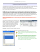
microHAM © 2008 All rights reserved Ports Tab Once the virtual ports have been created they must be associated with a specific device channel (e.g., Control, CW, PTT, etc.). These assignments should correspond to settings of the application software and must be configured first in Router then in the application (e.g., logging program, MMTTY, STREAM, etc.). Proper configuration of the port assigments in this tab is crutical for intergration with loggers. Read the following information carefully.
microHAM © 2008 All rights reserved CAT PORT & 2nd CAT PORT The CAT channel is used by application software to control transceiver frequency, mode, T/R switching and many other parameters using a serial (CAT) protocol. Most modern radios implement some form of CAT but almost every radio implementation is different. The functionscontrolled by the computer depend on the particular application and radio. NOTE: The port number assigned in Router MUST match the port number assigned in the host application.
microHAM © 2008 All rights reserved NOTE: "Disable router queries" disables Router polling only when the port has been opened by an application program. When the virtual port is closed, Router always polls the radio to support the automatic switching functions of microKEYER. If it is necessary to disable all polling, select one of the "none" options in the Radio box. PW1 on radio bus – When this box checked, Router periodically generates an Icom "Transceive" broadcast to keep the PW1 synchronized.
microHAM © 2008 All rights reserved FSK & 2nd FSK PORTS The FSK channel is used by the application program to send the FSK keying signal. FSK is used primarily for RTTY. It is very important to understand the difference between FSK and AFSK. FSK is a digital (On/Off) signal from the computer serial port (or an external modem). This signal is used in the transceiver to generate a frequency shift. FSK must be supported by the transceiver (this mode is commonly labeled RTTY or FSK).
microHAM © 2008 All rights reserved Invert: Some transceivers lack the ability to set the sense of the FSK input. If you cannot set the proper sense, check the invert box. This is normally necessary only with the TenTec Omni V, Omni VI and Kenwood TS-940. Strict bps: Some programs rely on the the FSK port for proper PTT timing; they drop PTT (unkey) when the FSK port buffer is empty. With virtual ports, this may cause PTT to drop before the contents of a message (macro) are complete.
microHAM © 2008 All rights reserved PTT & 2nd PTT PORTS The PTT channel is used for T/R switching of the transceiver, Power Amplifier and Low Noise Preamplifier (LNA). An internal T/R sequencer assures 100% protection against transmitting through the LNA or hot switching of the PA when the PTT channel is used for T/R switching. More information about T/R switching, DIGI KEYER PTT outputs and the sequencer is provided under the Keying Tab (page 21).
microHAM © 2008 All rights reserved KEYING TAB The Keying tab includes controls for the USB Audio processor, PTT and FSK Keyboard. Audio Note: Audio controls are not availble under Windows Vista due to operating system limitations. Transmit Level: sets the level of the audio output from the digital to analog converter. Preset the slider between 50 and 80% of full scale. Adjust the drive to your transceiver with the TX pot on the front panel of DigiKeyer.
microHAM © 2008 All rights reserved PTT – T/R KEYING DIGI KEYER has three (3) PTT outputs: PTT, PA PTT and LNA PTT. PTT is brought out to the DB15 Radio connector. PA PTT and LNA PTT are available on RCA connectors at the DIGI KEYER rear panel. PTT is normally wired to the radio Accessory jack and is used to switch the radio into transmit. PA PTT is present at the DIGI KEYER rear panel RCA jack and is designed for switching a power amplifier. PA PTT is enabled by checking the PA PTT box.
microHAM © 2008 All rights reserved FSK MESSAGES TAB DIGI KEYER allows defining nine messages of up to 50 characters each which are stored in non-volitile memory. Each memory may repeat with a programmable delay (loop) or call another memory (chain).
microHAM © 2008 All rights reserved 6 - EXTERNAL KEYBOARD DigiKeyer allows generating FSK signals from a PS2 keyboard attached to the Remote jack. TIP: The keyboard must be PS/2. A USB keyboard with PS/2 adapter will not function properly.
microHAM © 2008 All rights reserved 8 - WARRANTY microHAM warrants DigiKeyer for three (3) years. The product must not be modified in any way, except configuration or the warranty is voided. This warranty does not cover damage caused by improper or abnormal use, failure to follow instructions, improper installation, lightning, or excessive voltage. The product will be either repaired or replaced, at our discretion. The only cost will be the cost of return shipping.
microHAM © 2008 All rights reserved System Considerations DigiKeyer can be used with a wide variety of application packages. The capabilities of those packages will have a significant impact on the level of computing power required. “microHAM USB Device Router” must run with the application to provide an interface for the application and control of system functions.
microHAM © 2008 All rights reserved APPENDIX A – CONNECTORS Radio - DB15 Pin # Label Description 1 Power +13.
microHAM © 2008 All rights reserved APPENDIX B – APPLE OS 10 INSTALLATION 1. To Install DIGI KEYER in Apple's OS 10 prepare the DIGI KEYER as for your radio as shown on Page 4. 2. The proper USB drivers have been shipped with OS-X since version 10.5 (Leopard). OS-X should load the proper driver automatically when you connect the USB cable. 3. If your version of OS-X is missing the driver, copy the FTDI USB Driver disk image (.
microHAM © 2008 All rights reserved APPENDIX C – RFI Considerations A few guidelines to eliminate problems caused by RFI: 1. Proper grounding of all electronic equipment is critical. A modern station contains many, diverse, types of interconnected and interrelated equipment: transceiver, power amplifier, computer, control boxes, switch boxes, and power supplies. Each of these must be individually grounded with a sepearate connection to a single common ground point, thus forming a star ground connection.
microHAM © 2008 All rights reserved DECLARATION OF CONFORMITY Federal Communications Commission Statement (USA) This device complies with Part 15 of the FCC Rules. Operation is subject to the following two conditions: (1) this device may not cause harmful interference, and (2) this device must accept any interference received, including interference that may cause undesired operation. European Union Declaration of Conformity microHAM, s.r.o.