microHAM © 2010 All rights reserved DIGI KEYER II microHAM fax: +421 2 4594 5100 e-mail: support@microham.com homepage: www.microham.com Version 7.
microHAM © 2010 All rights reserved TABLE OF CONTENTS CHAPTER PAGE 1. FEATURES AND FUNCTIONS ......................................................................................................... 3 2. IMPORTANT WARNINGS ................................................................................................................ 4 3. PANEL DESCRIPTION ..................................................................................................................... 5 Front Panel ..................
microHAM © 2010 All rights reserved 1 - FEATURES AND FUNCTIONS No serial or parallel port required: just one USB cable between your computer and DIGI KEYER II Fully integrated: Sound Radio Control, true FSK, CW and PTT Computer sound card is not used Complete "Computer <-> Radio" electrical isolation transformer isolation between sound circuits and radio optical isolation between USB port and of ALL digital signals: Radio Control, CW, PTT, FSK, PA PTT, & LNA PTT Standard Sound Device -
microHAM © 2010 All rights reserved Independent keying buffers for Power Amplifier and LNA switching extended range solid state output for low voltage T/R lines or QSK relay isolated output for vintage PA with negative voltage T/R lines Bypass LNA before activating both PTT circuits for EME or scatter Footswitch input with programmable functions programmable PTT activation delay in 1ms steps selectable muting of CW and/or FSK when footswitch is closed Squelch input for signaling to comp
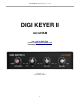
microHAM © 2010 All rights reserved 3 - PANEL DESCRIPTION FRONT PANEL (1) – POWER YELLOW color indicates when power is applied to the “Radio” connector. (2) – CW SPEED WinKey speed control. Range (MIN, MAX) is defined by software (3) – CW LED flashes with CW output (4) – Q-CW/P-FSK LED flashes with Right channel Audio output when properly configured for ON/OFF Keying (5) – TX Transmit Audio Level (6) – FSK LED flashes with FSK output. On indicates “closed” regardless of mark/space polarity.
microHAM © 2010 All rights reserved REAR PANEL All connectors for connecting the computer, radio and accessories are located on the rear panel. (1) RADIO: DB15F connector for radio interconnection – a detailed description is in Appendix A (2) MIC: 3.5mm jack for microphone input from micro2R (3) USB: USB B connector for computer connection. Connect the supplied USB A-B cable. (4) SUB RX: 3.
microHAM © 2010 All rights reserved (8) GND: Terminal for connection to station ground. (9) OUT: 3.5mm jack for output to micro2R (10) PADDLE 6.3mm (1/4") stereo female for paddle input. TIP: DIT RING: DAH SLEEVE: GND NOTE: The paddle sense can be reversed using Router settings (11) FOOTSW: input for optional foot switch (manual PTT) (12) LNA PTT: PTT output for controlling Low Noise Preamplifier or Receive antenna switching. See PAPTT for jumper assignments and specifications.
microHAM © 2010 All rights reserved 2. For Icom transceivers, install the ICVOX jumper located behind the PTT IN jack. Otherwise, connect your transceiver PTT Out (linear) to the PTT IN jack using the appropriate cable. 3. Connect your amplifier PTT (if used) to the PA PTT jack and set the PA PTT RE/SS jumpers appropriately. 4. Connect your keyer paddles to the PADDLE jack. 5. If you use a foot switch, connect the foot switch to the FOOTSW jack. 6.
microHAM © 2010 All rights reserved MICROSOFT WINDOWS (XP, Vista, Windows 7) INSTALLATION Installing microHAM USB Device Router To install Router click on the Install USB Device Router link on the installation CD or download the most recent installation package from the web site: www.microHAM.com/downloads.html. If you download an updated package, click on "urouter_release_xx_xx.exe" (xx_xx is version) to start the installation.
microHAM © 2010 All rights reserved Configuring microHAM CODEC Windows will automatically install the USB Audio Device driver to support the microHAM CODEC in DIGI KEYER II. Windows automatically selects any newly installed audio device as the default device for Sound Playback and Sound recording.
microHAM © 2010 All rights reserved Configuring microHAM USB Device Router The microHAM USB Device Router (Router) program provides a Windows compatible configuration tool for microHAM USB Devices and software interface to other Windows applications (loggers, digital mode software, etc.). The software interface is provided as Virtual Serial Ports.
microHAM © 2010 All rights reserved Creating and Using Virtual Serial Ports microHAM Router provides a set of virtual serial ports which allow Windows applications (loggers and digital software) to work with DK II just as they would work with "real" (hardware) serial ports. In order to use these virtual Ports, you must first create the ports and then assign a function (radio control, PTT, CW, FSK, etc.) to each virtual port.
microHAM © 2010 All rights reserved 5 - microHAM USB DEVICE ROUTER ROUTER MENU Default Router Settings: used to completely reset Router to factory (default) settings. "Default" removes all device tabs and deletes all stored configuration data, including all user presets. from the Windows Registry. TIP: DK II can be reset to the factory configuration by selecting Default Router Settings followed by Device | Store as Power-up Settings to save the defaults to the keyer's memory.
microHAM © 2010 All rights reserved Minimize: Clicking this will minimize Router to the system tray at the bottom right corner of the Windows Taskbar (the "System Notification Area"). TIP: When Router is minimized you can restore it by double-clicking on the Router tray icon. You can also restore Router by double-clicking on the Router icon on the desktop or restarting Router from the Programs menu. Exit: Clicking on this item will terminate Router.
microHAM © 2010 All rights reserved 3. By right clicking on the system tray icon when the Router is minimized. The presets and the current router configuration are stored to the registry when Router is closed and recalled when Router is loaded. Save as - Saves the current Router settings to a preset for future use. Rename - Allows renaming of an existing preset. Delete - Delete chosen preset. Show buttons - When checked, Router shows the preset buttons. DEVICE MENU Router can control several devices.
microHAM © 2010 All rights reserved Upload Firmware: microHAM will occasionally release updates to the firmware in DIGI KEYER II. The update may support news feature in Router or improve application compatibility. The recent public version of the firmware is always available from www.microHAM.com/downloads.html. To update firmware, download the firmware file to your computer, then click on Device | Upload Firmware.
microHAM © 2010 All rights reserved HELP MENU Manuals: Link to microHAM manuals located on your system. Setup Guides: Link to software configuration guides for many common applications. Cable Schematics: Link to cable diagrams. Download Documents: Downloads microHAM documentation including updated manuals and setup guides. You may specify the products for which you want documentation. NOTE: Download Documents requires an Internet connection. microHAM Home Page: Link to www.microHAM.
microHAM © 2010 All rights reserved Ports Tab Once the virtual ports have been created they must be associated with a specific device channel (e.g., Control, CW, PTT, etc.). These assignments should correspond to settings of the application software and must be configured first in Router then in the application (e.g., logging program, MMTTY, MixW, etc.). Proper configuration of the port assignments in this tab is critical for integration with logging and digital mode softwre.
microHAM © 2010 All rights reserved CAT PORT & 2nd CAT PORT The CAT channel is used by application software to control transceiver frequency, mode, T/R switching and many other parameters using a serial (CAT) protocol. Most modern radios implement some form of CAT but almost every radio implementation is different. The functions controlled by the computer depend on the particular application and radio. NOTE: The port number assigned in Router MUST match the port number assigned in the host application.
microHAM © 2010 All rights reserved PW1 on radio bus – When this box checked, Router periodically generates an Icom "Transceive" broadcast to keep the PW1 synchronized. NOTE: Check this box if you have an IC-PW1 or other Icom compatible accessory physically connected in parallel with the transceiver. Do not check this box if the only connection is to the transceiver and the PW1 or other other accessory is connected to the accessory CI-V port (described later).
microHAM © 2010 All rights reserved 2nd CAT PORT Beginning with version 7.0, Router provides unique control capability: the 2nd CAT Port is an intelligent data fork (software 'Y' connector) that allows a second application to share control of the radio. Router monitors when data is sent from each application and routes the radio's responses to the correct virtual port.
microHAM © 2010 All rights reserved An initial indication of proper audio drive level can be seen on the ALC meter of the radio. Provided that there is NO audio processing in circuit and that the microphone gain control is in its normal operating position, then, if the ALC does not show or just starts to indicate during transmission, the signal is likely to be clean. It is also important is to turn off the microphone compressor, ANY transmit audio equalizer, AND transmit DSP when AFSK is used.
microHAM © 2010 All rights reserved CW PORT By its very nature, USB is not well suited to transfer the real time events required for CW keying. In addition to the latency inherent in the USB protocol, delays due to CPU load, internal Windows message processing (inter-process communication) and data flow from another peripherals sharing same the USB root hub can result in transmitted characters that are garbled.
microHAM © 2010 All rights reserved FOOT SWITCH Even though many applications do not monitor the status of the foot switch and do not have the ability to perform specific functions base on closing or releasing the foot switch, we have decided to implement this feature to the Router. Hopefully sometime soon applications will be able to detect the foot switch status and use this this information for automating user functions like in the DOS based TRLog.
microHAM © 2010 All rights reserved WinKey PORT WinKey is a unique external CW processor developed by Steve Elliot, K1EL. This CW processor supports paddle input like any other electronic keyer, offers many configuration options, and in addition converts ASCII data from the computer to Morse characters. This unique property assures perfectly timed CW output from the computer regardless of OS load. More detailed instruction for configuring WinKey is found in the description of the CW/WinKey tab.
microHAM © 2010 All rights reserved The Control Protocol Monitor should not be needed under normal conditions. However, if there are problems with a particular logger, it may be useful to Start a capture and close the window. When a problem is noticed, the window can be opened and the Control protocol log Saved for analysis. The monitor log is circular – only the last 20 kilobytes or so will be saved in order to prevent creating very large files.
microHAM © 2010 All rights reserved AUDIO MIXER TAB Note: The Audio Mixer Tab is not present in Vista or Widows 7 due to operating system limitations. The sound card configuration depends on the capability of your application software. Some software can directly control the sound mixer controls some can not. Router's Audio Mixer tab provides the ability to store and recall level settings to the presets for each application (or operating configuration).
microHAM © 2010 All rights reserved TX VOICE/DIGITAL (transmit levels) These controls adjusts the output (transmit) levels. If the channels are active, the green rectangle will be on. If not, click the TX Mixer button and unmute the master Volume (Speaker) and Wave controls. There are two (or four) sliders, the WAVE slider and MASTER slider (the Master Volume or Speaker control). As a starting point, set the MASTER level to about 80% and the WAVE level to about 50%.
microHAM © 2010 All rights reserved PTT TAB DIGI KEYER II has three (3) PTT outputs: PTT, PA PTT and LNA PTT. PTT is brought out to the DB15 Radio connector. PA PTT and LNA PTT are available on RCA connectors at the DIGI KEYER II rear panel. PTT is normally wired to the radio Accessory jack and is used to switch the radio into transmit. PA PTT is present at the DIGI KEYER II rear panel RCA jack and is designed for switching a power amplifier. PA PTT is enabled by checking the PA PTT box.
microHAM © 2010 All rights reserved FOOTSWITCH SEQUENCER Additional functions can be associated with the footswitch (or hand mic PTT). DIGI KEYER II recognizes when the footswitch is closed (pressed) or open (released) and can manipulate CW, FSK, PTT and audio routing when the footswtich is closed or opened. Mute serial CW - if checked, serial CW (DTR or RTS) from an application program will be muted while the footswitch is pressed.
microHAM © 2010 All rights reserved CW / WinKey TAB This tab provides the configuration for the WinKey based, internal CW keyer. A complete WinKey manual can be downloaded from: http://k1el.tripod.com/docfiles.html. Thanks to Steve Elliott, K1EL for this great product. WinKey can be controlled by a logging program or operate in stand alone mode controlled by Router. Router controls the speed range, Paddle mode and other timing characteristics of WinKey.
microHAM © 2010 All rights reserved CW MESSAGES TAB On this tab you can define nine CW messages of up to 50 characters each which are stored in EEPROM. Each memory may have a programmable repeat delay and/or call another memory. Commands which may be included in a memory are: Merge: Cancel WPM: Set WPM: Set Key: Set Wait: merge two characters without a letter space – [M]AS will sound AS .-... restore speed set by the Speed pot. force speed to the selected value regardless of position of speed knob.
microHAM © 2010 All rights reserved FSK MESSAGES TAB DIGI KEYER II allows defining nine messages of up to 50 characters each which are stored in non-volatile memory. Each memory may repeat with a programmable delay (loop) or call another memory (chain).
microHAM © 2010 All rights reserved KEYBOARD TAB The Keyboard Tab controls the operation of a PS/2 keyboard or numeric keypad connected to the PS/2 jack. It is also possible to define control functions for the numeric keypad. Custom controls are invoked by pressing and holding the asterisk key (*) with Numkey0-9. General: QWERTZ layout – configures the keyboard for a QWERTZ layout. FSK from keyboard: Diddle LETTERS: send the LETTERS character whenever there is nothing in the transmit buffer.
microHAM © 2010 All rights reserved SYSTEM SETTINGS TAB System Power displays the input voltage at pin 1 of the Radio connector. CI-V port settings: The CI-V port will emulate an Icom transceiver and “broadcast” the frequency data if Router can determine it by polling the rig or reading polling data from the logging program. The transceive broadcast can be used to control peripherals that use Icom protocol.
microHAM © 2010 All rights reserved NOTE: For the Elecraft K3 and other transceivers that have a separate “line In” control, do not adjust the TX WAVE slider. Instead, adjust the Line In level until the ALC shows the correct level. 7. Set the RX RECORDING/DIGIAL sliders to approximately 80% and adjust receive audio levels with the RX MAIN and RX SUB controls on the front panel of DIGI KEYER II. 8. You may want to store these Router settings to the last preset.
microHAM © 2010 All rights reserved 3. Click the TX Mixer button. If the Mixer does not appear, open the Windows Sound Control Panel and select the "Playback" tab. 4. Click the "Test Signal" button on the Audio Devices screen and verify that the VU Meter for connected sound card reaches maximum. If not, turn off Test Signal, restart Router and return to step 1. Turn off the Test Signal. 5.
microHAM © 2010 All rights reserved 7 - EXTERNAL KEYBOARD/KEYPAD NOTE: The keyboard or keypad must be PS/2. A USB device with PS/2 adapter will not work properly. DIGI KEYER II includes the ability to generate CW/FSK or record and play CW/FSK messages using a keyboard or numeric keypad connected to the PS/2 jack. A numeric key pad will allow recording/playing CW messages, control CW speed (WPM) or play a serial number message. “Live” CW/FSK (RTTY) or storing FSK messages requires a full keyboard.
microHAM © 2010 All rights reserved std.
microHAM © 2010 All rights reserved 8 - System Considerations DIGI KEYER II can be used with a wide variety of software. The capabilities of those packages will have large influence on the level of computing power needed to utilize DK II.
microHAM © 2010 All rights reserved 10 - WARRANTY microHAM warrants this product for three (3) years. The product must not be modified in any way or the warranty is voided. Cables are warranted against defects in materials and workmanship for a period of 60 days. What is covered: During the warranty, microHAM, s.r.o., will repair or replace defective product at their sole discretion. You must send the unit postpaid with a copy of the original invoice to the distributor from whom you purchased the product.
microHAM © 2010 All rights reserved 11 - SPECIFICATIONS DIGI KEYER II is a multi-mode interface between computer and transceiver. It has been optimized for amateur digital modes and includes a high performance USB sound processor. DIGI KEYER II is connected to the computer using a single A-B USB cable which is included. The transceiver and DIGI KEYER II are connected by single radio cable terminated on one side by a DB15M and on the other side by the appropriate plugs for the specific transceiver.
microHAM © 2010 All rights reserved DECLARATION OF CONFORMITY Federal Communications Commission Statement (USA) This device complies with Part 15 of the FCC Rules. Operation is subject to the following two conditions: (1) this device may not cause harmful interference, and (2) this device must accept any interference received, including interference that may cause undesired operation. European Union Declaration of Conformity microHAM, s.r.o.
microHAM © 2010 All rights reserved APPENDIX A – CONNECTORS Radio - DB15 Pin # Label Description 1 Power +13.
microHAM © 2010 All rights reserved APPENDIX B – RFI Considerations A few guidelines to eliminate problems caused by RFI: 1. Proper grounding of all electronic equipment is critical. A modern station contains many, diverse, types of interconnected and interrelated equipment: transceiver, power amplifier, computer, control boxes, switch boxes, and power supplies. Each of these must be individually grounded with a separate connection to a single common ground point, thus forming a star ground connection.
microHAM © 2010 All rights reserved APPENDIX C – Tracking NOTE: Tracking is experimental code for linking the transceiver frequency to a tracking receiver begun in Router 7.5.0 . Mode linking and bidirectional frequency tracking are not currently supported. microHAM will be expanding features and adding support for additional radios in the future. The initial version has been tested with Perseus SDR only.