
User Manual


Page 5 of 32
MTI Proprietary
Table of Figures
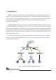
Figure 1 Example for usage of WiMAX outdoor CPE............................................................................................8
Figure 2 PoE Cable Connector, Grounding Screw, Status Indicator LEDs........................................................10
Figure 3 Ethernet Cable Connection to Host PC.................................................................................................11
Figure 4 Ethernet Cable Connection to XS-615-25X-XXX..................................................................................11
Figure 5 Power Cord Connection to PoE.............................................................................................................12
Figure 6 Greeting Page.........................................................................................................................................15
Figure 7 Login.........................................................................................................................................................15
Figure 8 System Information.................................................................................................................................16
Figure 9 Subscriber Capability..............................................................................................................................17
Figure 10 Network Setting.....................................................................................................................................18
Figure 11 WiMax Setting........................................................................................................................................19
Figure 12 MAC Address Clone..............................................................................................................................20
Figure 13 Channel Setting.....................................................................................................................................21
Figure 14 EAP Setting...........................................................................................................................................23
Figure 15 Subscriber Information..........................................................................................................................25
Figure 16 Service Flows Information....................................................................................................................26
Figure 17 Radio Information..................................................................................................................................27
Figure 18 MAC Uplink / Downlink Configuration..................................................................................................28
Figure 19 MAC Packet Data Unit..........................................................................................................................29
Figure 20 Downlink Physical Statistics.................................................................................................................30
Figure 21 File Upload.............................................................................................................................................31