
Installation Instructions
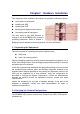

2-8 Connecting the cable
An
power to the ODU and allows Ethernet data to flow between Stations with Bridge
C power is
2-9 Align the Antenna (TBD)
Ethernet cable connects the ODU to the POE output port. The cable connects
system. Another Ethernet cable connects the station to POE input port. A
applied to the bridge system by connect it to POE AC adapter.
Notices
The RSSI BNC connector is still not function well now. Please
use the RSSI reading from the statistics window in WEB -base
browser.
Antenna alignment is performed with both the near-end and the far-end
ile monitoring the RSSI
alignment v her the RSSI voltage reading is, the
voltage reading is from 0 to 3.28VDC,
e resolution is 256 ns.
sure optimum performance, the main lobe of the antenna must be aligned
the antenna through the range of radiated power
n be positively identified. Each side lobe is approximately 20 dB lower than
be as you move away from the main lobe.
men dure is applicable to both protected and
o tions. Align the antenna as follows:
ced tial alignment does not produce the correct
ng.
sult your path ca n and adjust the radio’s attenuation level, so do
eed the max
idg far end is operational.
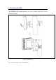
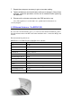
Bri ve the protective cap from the RSSI BNC
connector.
4. Connect a voltmeter to the RSSI connector and set the voltmeter to
measure VDC.
uth direction. Monitor the voltmeter and
locate the position where the voltage is minimum (null) and record the
ot the antenna in the elevation direction. Pivot
ltage is minimum on the voltmeter
terminals operating. The antenna position is adjusted wh
for antenna
stronger the signal. The range of the RSSI
oltage. The hig
and th divisio
Caution: To en system
with the center of the far end antenna. Rotate
so the main lobe ca
the preceding lo
This antenna align t proce
non-protected system c nfigura
Note: Repeat this pro ure if the ini
RSSI readi
1. Con lculatio
not exc imum receiving signal level.
2. Verify that the Br e at the
3. At the near-end dge, remo
5. Pivot the antenna slowly in the azim
reading.
6. Monitor the voltmeter and piv
the antenna to the position where the vo
and record the reading.