
Data Sheet

Technical Specifications
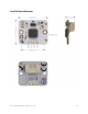
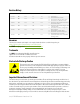
Physical
Size: 21mm x 25mm x 8.3mm
Weight: approx 2.5grams
Mounting: 2x plated holes which are 2.0mm in diameter and spaced 20mm apart (both are
connected to the circuit ground). Designed for mounting with M2 type screws.
Operating Temperature
-20 to +70C
Power Consumption
Operation Voltage: 3v to 5v DC (2.8v operation is possible with a regulated voltage source)
Quiescent Current: <3uA measured at 2.8v supply in single step, tinyLiDAR mode
Average Current: approx. 24mA measured at 3.3v supply in continuous, tinyLiDAR mode
Bus Interface
I2C Rate: 100Kbps fixed
I2C Levels: 3v to 5v (i.e. same as supply voltage)
I2C Pull-up resistors: 2x 4.7K SMD (user accessible PCB traces on top layer can be cut if desired)
I2C Default Address: 0x10 (can change with I2C command)
Bus Connectors
1x Right-Angled 4pin GROVE type universal connector
4x PCB edge “castellated” half-pads at 0.1inch centers
4x 0.1inch pads for header pins
Optical
Field of View: 25degrees
940nm (IR) VCSEL Class 1 Laser {as per ST’s datasheet: “
The laser output is designed to remain
within Class 1 laser safety limits under all reasonably foreseeable conditions including single
faults in compliance with IEC 60825-1:2014 (third edition).
*“ }
Activity Indicator: Blue LED (can be disabled with I2C command)
Performance
Accuracy: +/-3% typical up to 1.2m in High Accuracy mode*
Sensing Distance: approx. 3cm to 2meters
Sample Rate: 60Hz max in continuous mode
* please see VL53L0X datasheet for further details.
tinyLiDAR Reference Manual rev1.26 32