tinyLiDAR Reference Manual © 2018 MicroElectronicDesign, Inc. www.microed.co Rev 1.
Table of Contents Introduction Features Example Code Serial (TTY) Log Output I2C pull-up resistors 3 5 6 6 7 I2C commands Read Distance 8, 12 LED Disable 8, 12 LED Enable 8, 13 LED On 8, 13 Continuous mode 8, 15 Single Step mode 8, 16 Real Time mode 8, 16 Change I2C address 8, 17 Reboot only 8, 13 LED mode save with reboot 8, 14 Reset to factory defaults Write custom VL53L0X config Preset Ranging mode Auto-Calibrate Distance Offset Auto-Calibrate Crosstalk Disable WatchDog Timer Enable WatchDog Timer Quer
This page was intentionally left blank tinyLiDAR Reference Manual rev1.
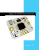
Introducing tinyLiDAR The Maker-Friendly Laser Sensor Have you heard of LiDAR? Chances are that you probably have. It’s fast becoming the new buzzword in the news lately. It’s the cool new tech that can be found in all sorts of new products like driverless cars, drones and even smartphones. So what is it? LiDAR stands for "Light Detection and Ranging" and if you Google it, you’ll find a bunch of references to long range airborne surveying systems. That was the old-school LiDAR.
Ultrasonic sensors were our first choice but we found them to be inaccurate, slow and power hungry. The new ST ToF sensors also seemed to fit the bill nicely.
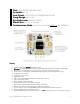
Fast up to 60Hz sample rates Accurate to 3% Low Power <3uA stdby in SingleStep mode Long Range up to 2m Eye Safe Laser 940nm Class 1 Small Size 21 x 25 x 8.3mm Autonomous Mode runs at low power without an Arduino! Features • • • • • • • • • • • • • • • • Advanced Technology: Eye safe VCSEL Class 1 Laser Ultra Fast: up to 60Hz sample rates and up to approx 930Hz I2C reading rates even with an Arduino UNO. Accurate: to +/-3% with mm precision. Every unit is pre-calibrated by us before shipping.
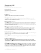
Example Code The sketch below gives you an idea of the minimal code required to talk to tinyLiDAR from an Arduino UNO. Compiled size is only 2396 bytes! • Note that although this sketch can provide data at up to 75Hz using the default single step mode, new data is available at “only” up to approx a 60Hz scan rate. If desired, even faster reading rates of up to approx 930Hz are possible - see Appendix A for details. void setup() { Serial.begin(115200); I2c.
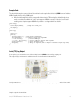
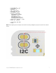
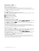
> > > > > > > tinyLiDAR FW: 1.4.0 ST PAL API: 1.0.2 WatchDog: on LED: measurement LongTimer Cal: Yes I2C Address: 0x10 Presets: tinyLiDAR SignalLimit 0.10 Mcps SigmaLimit 60 mm TimingBudget 18 ms PreRangeVcselPeriod 18 FinalRangeVcselPeriod 14 > Offset Cal: Default = 35 mm > Xtalk Cal: Default -> SingleStep ULP Mode > Ready Note: The I2C pull-up resistors maybe removed from circuit by cutting the top layer traces in the area shown below. tinyLiDAR Reference Manual rev1.
I2C commands for tinyLiDAR D Read Distance 0x44 Read distance in mm from the most recent measurement E LED Disable 0x45 Disable the on-board Blue LED indicator. F LED Enable 0x46 This will make the LED blink for each measurement taken. G LED On 0x47 This will turn on the LED and keep it on regardless of measurements. MC Continuous mode 0x4d 0x43 Set tinyLiDAR to continuous conversion mode. This is the lowest latency and highest power mode of the module.
I2C commands for tinyLiDAR (cont’d) W Write custom VL53L0X config 0x57… Write new VL53L0X configuration parameters. Parameters are written in the following order: Signal Limit, Sigma Limit, Time Budget, VCSEL Period selection. This command requires a sequence of steps which are best understood by following the code from the tinyLiDAR Terminal GUI sketch shown in Appendix A. P_ Preset Ranging mode 0x50… Set tinyLiDAR to one of 4 Ranging modes: L,S,H,T as described below.
I2C commands for tinyLiDAR (cont’d) WatchDog Timer The hardware WatchDog Timer will automatically reboot tinyLiDAR if no I2C bus activity is seen in approx 7 seconds. This feature is essential for long term reliabilty as the watchdog timer is an independent circuit inside of the microcontroller and can automatically reset itself if the code locks up for any reason. When the watchdog timer triggers it will print a period on the serial log terminal output and reboot the tinyLiDAR sensor quickly.
I2C commands for tinyLiDAR (cont’d) A Autonomous mode start (available since FW: 1.3.8) 0x41… Set tinyLiDAR to a host controller-less Single Step Ultra Low Power conversion mode. This is a new lower power mode of the module where it will take a measurement continually at a specified cadence and stay in the lowest power state otherwise. A trigger threshold distance must be programmed before this mode can be started.
D Read Distance 0x44 Read distance in mm from the most recent measurement Host -> Sensor Send Command 0x44 {D} Sensor -> Host Read Response 2 bytes with MSB first Example: Read from distance from tinyLiDAR at default address of 0x10. Value read was 0x0690 or 1680mm. <10:w> 44 <10:r> 06 90 E LED Disable 0x45 Disable the on-board Blue LED indicator. Host -> Sensor Send Command 0x45 {E} Example: Disable the LED indicator on tinyLiDAR at default address of 0x10. <10:w> 45 tinyLiDAR Reference Manual rev1.
F LED Enable 0x46 This will make the LED blink for each measurement taken. Host -> Sensor Send Command 0x46 {F} Example: Enable the LED indicator on tinyLiDAR at default address of 0x10. <10:w> 46 G LED On 0x47 This will turn on the LED and keep it on regardless of measurements. Host -> Sensor Send Command 0x47 {G} Example: Set the LED to be on. <10:w> 47 X Reboot only 0x58 Reboot tinyLiDAR immediately without writing any settings to non-volatile storage. Please allow some time for it to reboot.
Y LED mode save with reboot 0x59 Same as the X command but also writes the LED indicator mode to nonvolatile storage. Note that this command will cause tinyLiDAR to write this mode to non-volatile memory and reboot. Therefore please allow some time for it to reboot. Host -> Sensor Send Command 0x59 {Y} Example: Save LED mode and reboot now. <10:w> 59 RESET Reset to factory defaults 0x00 0x06 Reset tinyLiDAR to the default board address of 0x10 and clear user settings.
MC Continuous mode 0x4d 0x43 Set tinyLiDAR to continuous conversion mode. This is the lowest latency and highest power mode of the module. Note that this command will cause tinyLiDAR to write this mode to non-volatile memory and reboot. Therefore please allow some time for it to reboot. Host -> Sensor Send Command 0x4d {M}, 0x43 {C} Example: Set tinyLiDAR to continuous mode at default address of 0x10. <10:w> 4d 43 tinyLiDAR Reference Manual rev1.
MS Single Step mode 0x4d 0x53 Set tinyLiDAR to single step conversion mode. This is the lowest power mode of the module where it will take a measurement on demand only (using the D command) and stay in the lowest power state otherwise. Note that this command will cause tinyLiDAR to write this mode to non-volatile memory and reboot. Therefore please allow some time for it to reboot. Host -> Sensor Send Command 0x4d {M}, 0x53 {S} Example: Set tinyLiDAR to single step mode at default address of 0x10.
I Change Terminal’s I2C address Change the I2C address for the Arduino I2C Host. This address will be used as the new target address to talk to the connected tinyLiDAR module. Note this is only a Host side command and does not send anything to tinyLiDAR. Example: Set the terminal to address the new target at I2C address of 0x22. Enter the following on the terminal screen: i 22 R Change I2C address 0x52… Change the I2C address for tinyLiDAR.
W Write custom VL53L0X config 0x57… Write new VL53L0X configuration parameters. Parameters are written in the following order: Signal Limit, Sigma Limit, Time Budget, VCSEL Period selection. This command requires a sequence of steps which are best understood by following the code from the tinyLiDAR Terminal GUI sketch shown in Appendix A. Host -> Sensor Send Command 0x57 {W}, Signal Rate Limit in MCPS written as 100x the required value, {required range is 0.00 to 65.
CD Auto-Calibrate Distance Offset 0x43 0x44… Perform Offset Distance Calibration on tinyLiDAR. Before using this calibration command, please set tinyLiDAR to Continuous, High Accuracy mode by issuing the commands “MC” and “PH”. ST recommends to use a distance of 100mm to a white (88% reflectivity) target. Therefore, place a white target 100mm away from tinyLiDAR before running this calibration. Must specify calibration distance in mm.
CX Auto-Calibrate Crosstalk 0x43 0x58… Perform Crosstalk Calibration on tinyLiDAR. This correction factor is typically not used as it is meant to try and correct for crosstalk from thin cover windows placed in front of the sensor. The tinyLiDAR module does not ship with a cover window hence it does not require crosstalk correction by default. Before using this calibration command, please set tinyLiDAR to Continuous, High Accuracy mode by issuing the commands “MC” and “PH”.
P_ Preset Ranging mode 0x50… Set tinyLiDAR to one of 4 Ranging modes: L,S,H,T as described below. Note that this command will cause tinyLiDAR to write this mode to nonvolatile memory and reboot. Therefore please allow some time for it to reboot. You can also set to custom formats using the “W” command. PL: long range mode (up to 2m, 33ms) PS: high speed mode (up to 1.2m, 20ms) PH: high accuracy mode (up to 1.
Q Query Settings 0x51 This command will provide the current tinyLiDAR module settings: • • • • • • • • • • • • • • Current Operation Mode: {single step or continuous} WatchDog Timer: {on/off} LED Indicator: {on/off/measurement} Current Preset Configuration: {HighSpeed/LongRange/HighAccuracy/tinyLiDAR /Custom} Signal Rate Limit (in MCPS) Sigma Estimate Limit (in mm) Timing Budget (in ms) Pre Range VCSEL Period Final Range VCSEL Period tinyLiDAR Firmware Version ST PAL API Version Offset Cal: {custom or def
[14] bit 3 for Offset Cal flag. Set means “custom” else “default” settings being used currently by tinyLiDAR. [14] bits 2 and 1 for LED Indicator mode. • 00 means ‘OFF’. • 01 means ‘ON’. • 10 means ‘Measurement’ mode. [14] bit 0 for WatchDog Timer flag. Set means “ON” else “OFF”. [15][16][17][18] for Offset Cal value. Scale down by 1000 for proper value in mm. [19][20][21][22] for Crosstalk Cal value. Scale down by 65536 for proper value in MCPS.
T0 Disable WatchDog Timer 0x54 0x30 This command will turn off the watchdog timer in the non-volatile settings and cause a reboot. Therefore please allow some time for it to reboot. Host -> Sensor Send Command 0x54 {T} 0x30 {0} Example: Turn off the WDT. <10:w> 54 30 T1 Enable WatchDog Timer 0x54 0x31 This command will turn on the watchdog timer in the non-volatile settings and cause a reboot. Therefore please allow some time for it to reboot.
A Autonomous mode start (available since FW: 1.3.8) 0x41… Set tinyLiDAR to a host controller-less Single Step Ultra Low Power conversion mode. This is a new lower power mode of the module where it will take a measurement continually at a specified cadence and stay in the lowest power state otherwise. A trigger threshold distance must be programmed before this mode can be started.
Example: Set to detect object in 10 to 200mm range and output a pulse width of 1sec with LED indicator showing when measurements are taken and when it is triggered. Take measurements every 3 seconds. Note: measurement type should be setup prior to this (i.e. high accuracy mode, etc.) Enter command on Terminal GUI as: A 10 200 30 10 1 Command 'A': Autonomous Mode.
U Start Ultrasonic Emulation mode (available since FW: 1.3.9) 0x55 Sets tinyLiDAR to output distance information using pulse width modulation instead of I2C. Setup tinyLiDAR to desired measurement parameters before running this mode. The “trigger” input pin will be the yellow (SCL) pin and the “echo” output will be on both the yellow (SCL) and white (SDA) pins.
UZ End Ultrasonic Emulation mode (available since FW: 1.3.9) Stops the tinyLiDAR Ultrasonic Emulation mode and enables the I2C port again for normal host controller based operation. This command requires a sequence of steps which are best applied from the tinyLiDAR Terminal GUI sketch shown in Appendix A. Additional Steps: To bring the tinyLiDAR board out of this ultrasonic emulation mode you need to issue the UZ command (via the I2C bus pins) while also pressing the RESET button on the tiny board.
B Start Autonomous IoT mode (available since FW: 1.4.1) 0x42 … Set tinyLiDAR to a host controller-less Single Step conversion mode. Using this command, tinyLiDAR will run continously in one of two modes: Object Detection Mode: An object placed within the pre-programmed sensing range will cause the SDA line to be pulled low. tinyLiDAR Reference Manual rev1.
State Tracking Mode: An object brought closer than the pre-programmed trigger threshold will cause the SDA line to be pulled low. Removing the object beyond the pre-programmed release threshold will cause the SDA line to be released to high. All necessary parameters must be programmed before this command will start. See details in the GUI Terminal Sketch ver 1.26 or higher. No I2C host such as an Arduino etc is needed for operation once tinyLiDAR is in this mode.
Examples: Set to detect object in 100 to 200mm range with LED indicator showing when measurements are taken and when it is triggered. Take measurements every 500ms. Note: measurement type should be setup prior to this (i.e. high accuracy mode, etc.) Enter command on Terminal GUI as: B 1 100 200 500 1 Command 'B': Autonomous IoT Mode.
Technical Specifications Physical Size: 21mm x 25mm x 8.3mm Weight: approx 2.5grams Mounting: 2x plated holes which are 2.0mm in diameter and spaced 20mm apart (both are connected to the circuit ground). Designed for mounting with M2 type screws. Operating Temperature -20 to +70C Power Consumption Operation Voltage: 3v to 5v DC (2.8v operation is possible with a regulated voltage source) Quiescent Current: <3uA measured at 2.8v supply in single step, tinyLiDAR mode Average Current: approx.
Wiring Diagram Original Concept tinyLiDAR Reference Manual rev1.
Front/Side Views & Dimensions Rear View tinyLiDAR Reference Manual rev1.
Appendix A Sample Arduino UNO Sketches for tinyLiDAR Link to all downloads: https://microedco.s3.amazonaws.com/index.html tinyLiDAR Reference Manual rev1.
/* Arduino UNO sketch to check response rate for tinyLiDAR It will run a number of readings as fast as possible and give the effective response rate in Hz. (showed over 930Hz in our lab testing) Last Edit: Oct 23, 2017 Copyright (c) 2017 by Dinesh Bhatia This program is free software: you can redistribute it and/or modify it under the terms of the GNU General Public License as published by the Free Software Foundation, either version 3 of the License, or (at your option) any later version.
Arduino UNO sketch to show minimal coding required to read distance from tinyLiDAR This program will continually print the measured distance from tinyLiDAR which is operating in its default single step mode. Last Edit: Oct 23, 2017 Copyright (c) 2017 by Dinesh Bhatia This program is free software: you can redistribute it and/or modify it under the terms of the GNU General Public License as published by the Free Software Foundation, either version 3 of the License, or (at your option) any later version.
Revision History Date Author Firmware GUI Term Ref Manual 10/2017 DB 1.3.7 1.0 1.0 12/2017 DB 1.3.8 1.1 1.21 1/2018 BM 1.3.9 1.23 1.22 1/2018 BM 1.3.9 1.24 1.