Mercury 1000 ™ Analog Output Encoder System Installation Manual and Reference Guide Manual No.
Introduction MicroE Systems was founded to advance encoder technology to a level never before achieved. Our objective was to design encoder systems that would be small enough to fit into densely packed OEM equipment designs, affordable enough for cost-sensitive applications and easy enough to enable installation, setup and alignment by assemblers with little training. We are pleased to say that all of these goals have been realized with the introduction of the Mercury family of encoders.
Table Of Contents SYSTEM ILLUSTRATION Encoder with Linear scale Encoder with Rotary scale PAGE 2 3 INSTALLATION INSTRUCTIONS Encoder System Mounting - Linear Encoder System Alignment - Linear Establishing an Index - Linear Centering the Index & Calibration - Linear Encoder System Mounting - Rotary Encoder System Alignment - Rotary Establishing an Index - Rotary Centering the Index & Calibration - Rotary 4 5 5 5 6 7 7 7 REFERENCE SECTION Installation of Linear Scales Grounding Instructions Recommendation
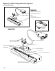
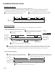
Mercury 1000 Analog Encoder System with Linear scale System View Shown with linear scale 15 pin standard D-sub connector Sensor Linear glass scale (shown mounted on a linear slide) SmartPrecisionTM Alignment Tool SS-AT 1000 Expanded View Mounting screws & flat washers (2 needed per screw) Optional sensor benching pins (3) Double shielded cable Sensor mounting holes (2) End locator pin Typical user-supplied sensor mounting bracket Center index mark Bracket mounting holes (2) Scale reference datum;
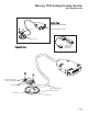
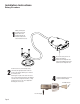
Mercury 1000 Analog Encoder System with Rotary scale System View Shown with rotary scale sensor 15 pin standard D-sub connector Rotary glass scale SmartPrecisionTM Alignment Tool SS-AT 1000 Expanded View Mounting screws & flat washers (2 needed per screw) Mounting hole (2) Double shielded cable Top reflective rotary scale Index mark Rotary scale Page 3
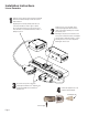
Installation Instructions Linear Encoders 1 Attach the scale to the base slide. Reference the preferred datum on the interface drawing for either end or center index orientation. Depending on the mounting method, attach the scale to the slide with adhesive. Refer to pg. 8 for details. Be sure the grating surface of the scale faces the sensor. Insure that there is no contact between these surfaces or damage may result.
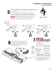
Installation Instructions Linear Encoders The red, yellow, or green LED will light depending on sensor alignment. Slowly move the sensor by allowing it to slide on the mounting surface until the green LED, is illuminated. Optimal alignment will be displayed as a “Bright Green” LED. x Y 5 θz Proper sensor alignment may require minor adjustments to the sensor position with respect to the scale. This can be performed easily using the SmartPrecisionTM Alignment Tool as illustrated below.
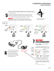
Installation Instructions Rotary Encoders 1 2 Attach your hub/scale assembly to the rotary device. Refer to the interface drawing. The reflective surface of the scale must face the sensor. 4 Connect the Alignment Tool to the Computer Interface Adapter. Install the sensor on your mounting surface referencing the appropriate datum surface as shown on the interface drawing. Use 2 washers per mounting screw. Benching pins may be used to locate the sensor if the system mechanical tolerances are adequate.
Installation Instructions Rotary Encoders θz Proper sensor alignment may require minor adjustments to the sensor position with respect to the scale. This can be performed easily using the SmartPrecisionTM Alignment Tool as illustrated below. x Y 5 The red, yellow, or green LED will light depending on sensor alignment. Slowly move the sensor by allowing it to slide on the mounting surface until the green LED, is illuminated. Optimal alignment will be displayed as a “Bright Green” LED.
Installation Reference Guide Positioning the Scale Note: Before beginning mounting procedure, use talc-free gloves or finger cots to handle the scales. "Benching" the scale to the system means aligning the scale by means of benching pins. Pin locations are described on the appropriate interface drawing. Two benching pins are recommended on the long side of the scale and one at the end as shown . This is marked datum A on the interface drawing. the benching pins in from either end.
Installation Reference Guide Grounding Instructions for Mercury 1000 Encoder System For Mercury 1000 encoder systems to operate reliably, it is essential that the sensor and cable shield are grounded properly according to the following instructions. The diagrams below show how to make the connections when the encoder's connector is plugged into the customer's controller chassis.
Customer Differential Amplifier Recommended Interface Termination A+ Sine+ R 120 ohm ASine- Cosine+ B+ R 120 ohm BCosine- IW+ IW+ R 120 ohm IWIW- Customer Interface Cable Requirements Customer cables that interface to Mercury series encoders must have the following characteristics: • Twisted pair signal wiring. • Characteristic impedance of 100-120 ohms. • Sufficient wire gauge to meet the minimum voltage requirement at the encoder, for example 24AWG gauge wire for a 2m length cable.
Troubleshooting Problem The Power/Calibration indicator will not come on. Solution • Make sure the M1000 15-pin D connector is fully seated and connected. • Confirm that +5 Volts DC is being applied to pin 12 on the M1000 15-pin D connector and that pin 13 is connected to ground. Problem Can't get the SmartPrecisionTM Alignment Tool "Signal" LEDs better than red or yellow; or the green, “ green” indicator doesn't stay illuminated over the full length of the scale.
Contacting MicroE Systems Thank you for purchasing a MicroE Systems product. You should expect the highest level of quality and support from MicroE. If you want to download the Mercury Encoder Installation Manual, Data Sheet or Interface Drawing, browse www.microesys.com and click on the Mercury Encoders button. World Headquarters: 125 Middlesex Turnpike • Bedford • MA 01730 USA www.microesys.com • info@microesys.com • T. [781] 266-5700 • F.